Digital Clock
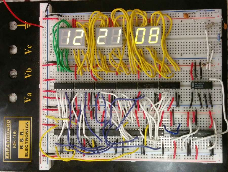
Made for EE 22100, this is a 12 hour digital clock that displays hours, minutes, and seconds. It uses a 32Mhz Quartz crystal to generate the clock frequency and then output it to an array of 7 segment LED displays. Through making this, I really got a much better grasp on the concepts from the digital logic class I took back in fall semester 2014. There's really nothing like actually building something to cement your knowledge of material.
Luckily I'd started studying this stuff over Christmas, so I already knew my way around a breadboard and had a wire stripper that, unlike the one included in the lab kit, didn't totally suck. My class was the first EE Lab I class to be assigned this particular project. With the instruction manual still in beta, we were basically given a parts list and told to figure out how to use them to build a clock. It was really stressful, but luckily we live in the age of the internet. I got a lot better at reading datasheets as a result.
For most of us, it was our first time wiring a breadboard with this many wires. Organization is KEY. If you have a chaotic jungle of wires with no sensible color scheme, you won't be able to efficiently troubleshoot your circuit. It's important to trim your breadboard wires down to appropriate lengths, too.
Parts List
3 x HDSP-5721
1 x 32MHz quartz crystal
2 x 33pf ceramic capacitors
1 x 10M resistor
1 x 330K resistor
Chips used for the clock signal:
1 x CD4069CN
2 x HCF4520RF/BE
1 x CD4081
Chips used for the display:
2 x CD4543BE (hours)
2 x CD4510BE (hours)
2 x MC14543B (min/sec)
2 x CD4518B (min/sec)
Writeup
The counters:
For the counters, two separate kinds of chips were used. The 4510 was used for the hours display, and the 4518 was used for the minutes and hours displays. Both chips serve a similar function. They count up until a certain number, and then reset. However, the 4510 has the ability to customize which number you reset back down to. This is desirable for the hours display, because we want it to count from one to twelve, not zero to twelve. For the minutes and hours displays, which we want to count from 00 to 59, this ability to customize what number the reset returns to is not necessary. Thus, the 4518 was chosen for inclusion in the lab kit. The 4518 lacks the ability to customize the return value, but can control two 4543 chips (and their corresponding two 7 segment displays) compared to the 4510’s ability to control only a single 4543 chip (and corresponding display).
These functions were made possible by using a 4081 quad AND gate chip which takes two inputs and produces an output when both inputs are high. For example, setting one and gate to trigger off of a 0001 and 0111 signal coming from the 4518 chips forces the hours display to reset when the first digit is 1 and the second digit attempts to change to 3.
The first 4518 receives the clock signal and counts from 00 to 59. When it reaches 59, it resets to 0 after the next second passes, and passes the clock signal on to the minutes counter, the other 4518. The 4518 repeats the same process for the hours counters, the two 4510s.
The display:
The display uses three HDSP-5721 pieces—one for the hours, one for the minutes, and one for the seconds. Each 5721 has a left digit and a right digit, and each digit is formed by a 7 segment LED display. Each of the 7 segments is given a letter ranging from a to f. Using a 4543 BCD to 7 segment driver chip, the binary signal coming from the counter chips (4510/4518) is transformed into the output signals ranging from a to f, which in turn light up one of the 7 segments of the display. and translates it into a to f.
Time setting circuitry and the switch bounce problem:
There was insufficient time remaining to complete custom time setting circuitry, which was an optional task assignment. A rough work around could be found by either setting the clock signal to run fast (by moving the clock output wire 1-2 units to the right on the last 4520 chip) or by touching a positive wire to the inputs on the chips directly to send a manual pulse signal to trigger the cascade. Switch bounce occurs when the switch contact registers as several inputs rather than a single one, which can cause the input to skip several digits instead of just the one. There are several ways to fix this issue—the first is to install something in the hardware, such as a combination of a resistor and a capacitor, that will determine the response speed of the switch. The second would be to use a microcontroller to detect the multiple spikes indicating “bounce” and then programming the software to disregard additional inputs for some set amount of time after registering the first one.
Generating the clock signal:
The time base generator was first simulated by using a function generator set to a square sine wave output and later by installing a 32 MHz quartz crystal onto the breadboard. A 32Hz crystal was chosen because lower frequencies (such as the 16Mhz quartz crystal) provide less accurate timekeeping, and are also more bulky. Two capacitors and two resistors were used to buffer and protect the crystal and also to step down the voltage. The output from the crystal was passed to a 4069 amplifier chip, which was then routed to a pair of 4520 chips to divide the clock signal down to 1 second. This output was then linked up to the clock input of the first 4518 chip (for the seconds counter).
How long will this thing run on 9V or AAA batteries?
A 9V battery is the same as 6 x 1.5 V, or 6 AA batteries. This clock would be better off attached to a wall power supply since a 9V power supply will not run it for very long—likely an hour or less. According to the data sheet, the typical forward current per LED is 20mA, and we have 6 digits with 8 segments each. This totals to 960mA if all 8 segments on all six digits were lit continuously. Although only a few segments per digit may be lit at a time during normal operation, if we assume that half the segments are on and half are off, resulting in, say, a 500mA current draw, it will still have a very limited operating time--a 9V battery only has between 400-600mAH. The logic portion of the clock draws very little current compared to the LED displays, so long as all the unused inputs of the chips are properly grounded. An LCD display is a common choice for projects such as this because it draws much less current than LED display types such as the ones we used.