Easily the most ambitious part of the whole thing, since I was wading deep into unknown territory here.
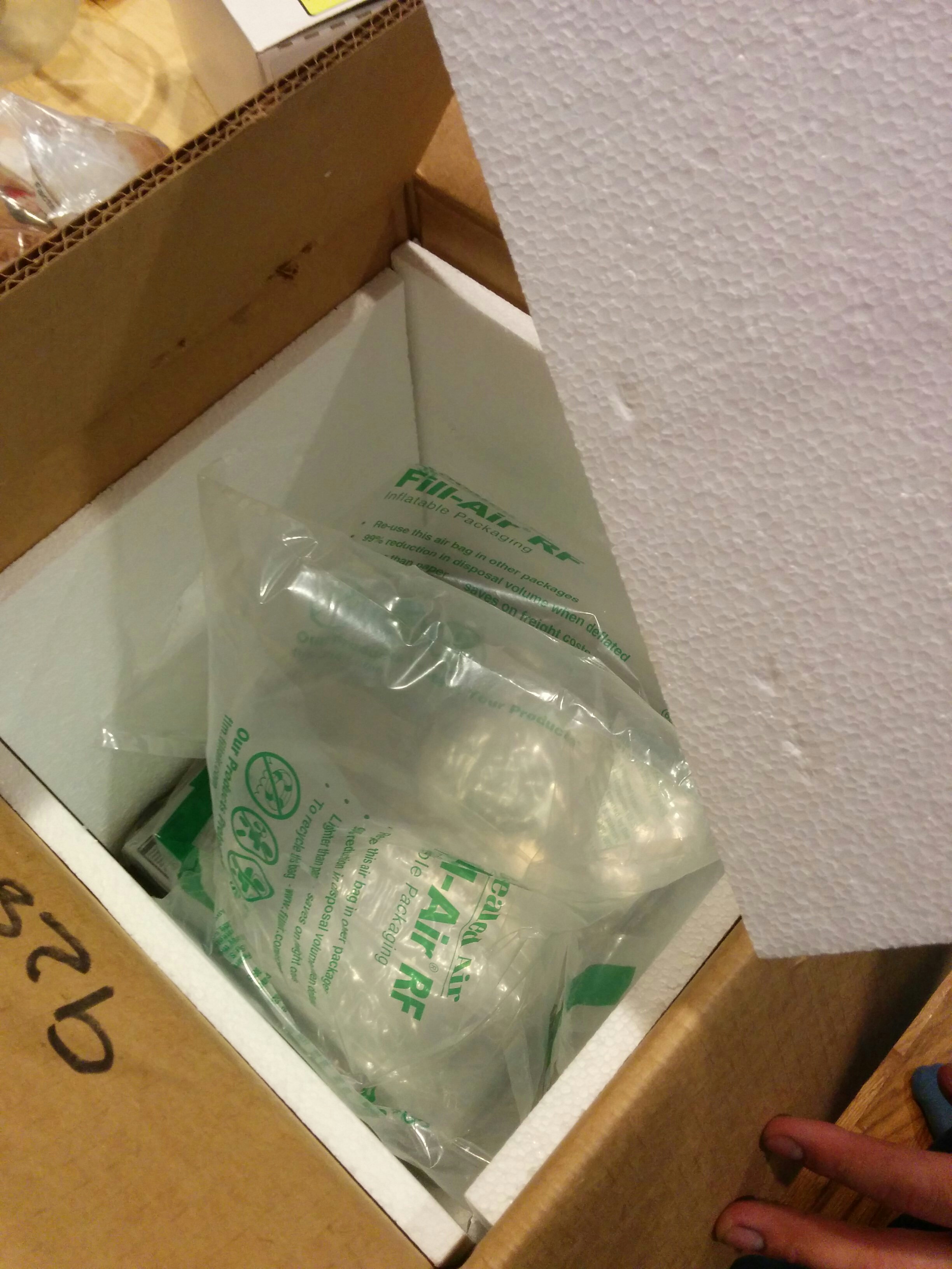
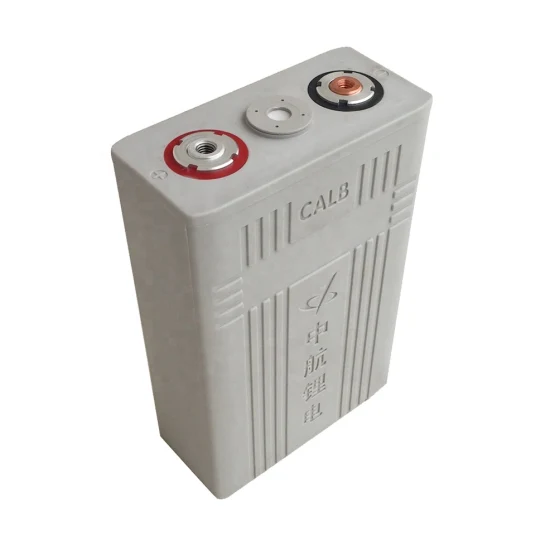
I ordered my LiFePO cells from the straightforwardly named Electric Car Company. At the time, you had to email them what you wanted so they could manually compute the shipping cost and send you a paypal request for payment. It was all very retro. I needed 4 cells which cost $82.50 each. The UPS shipping cost $80.00, bringing the total to $410.00. This was quite a lot of money for me at the time.
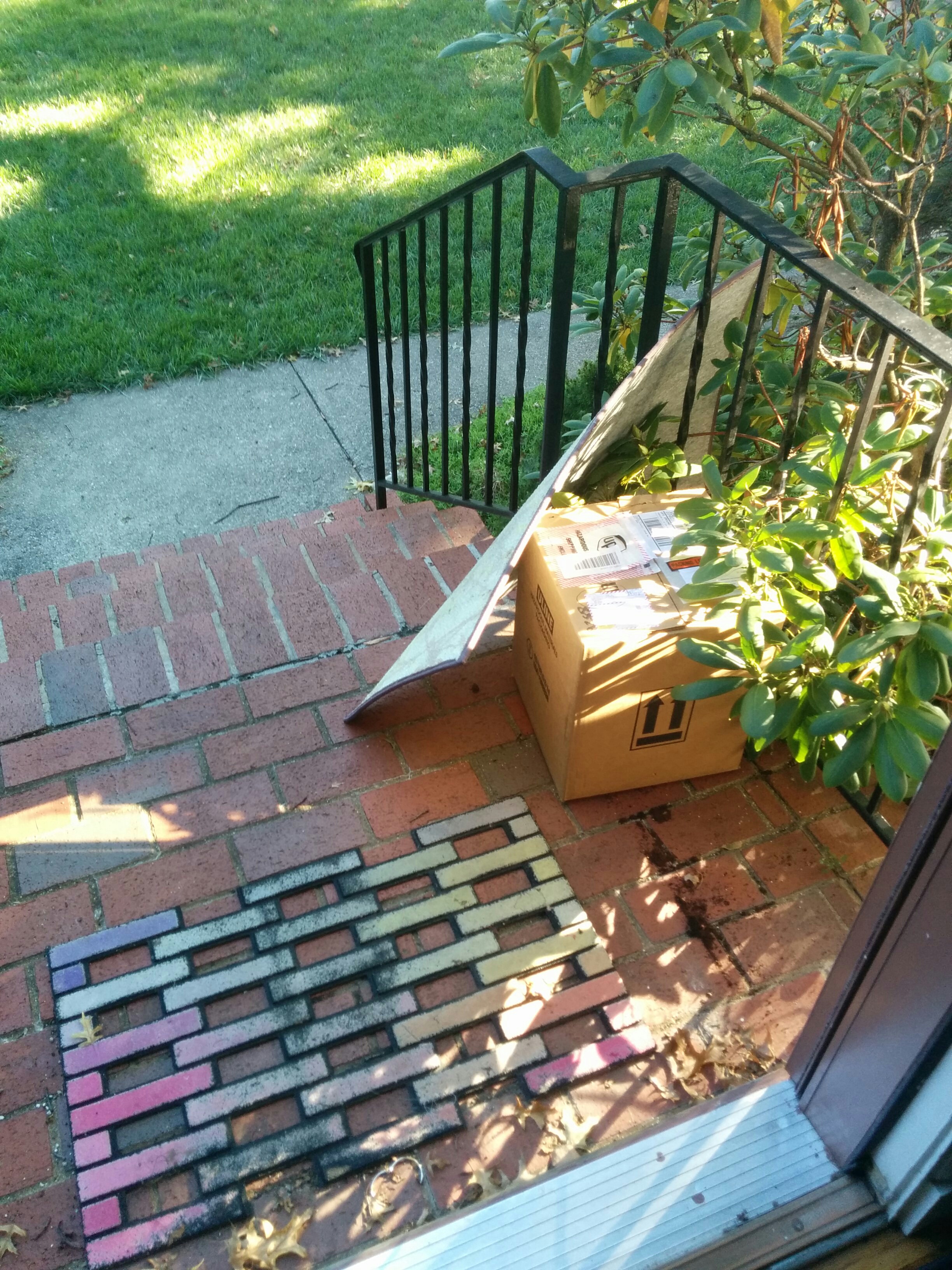
I appreciated the effort at hiding them but this was very funny to wake up to.
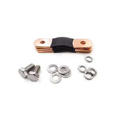
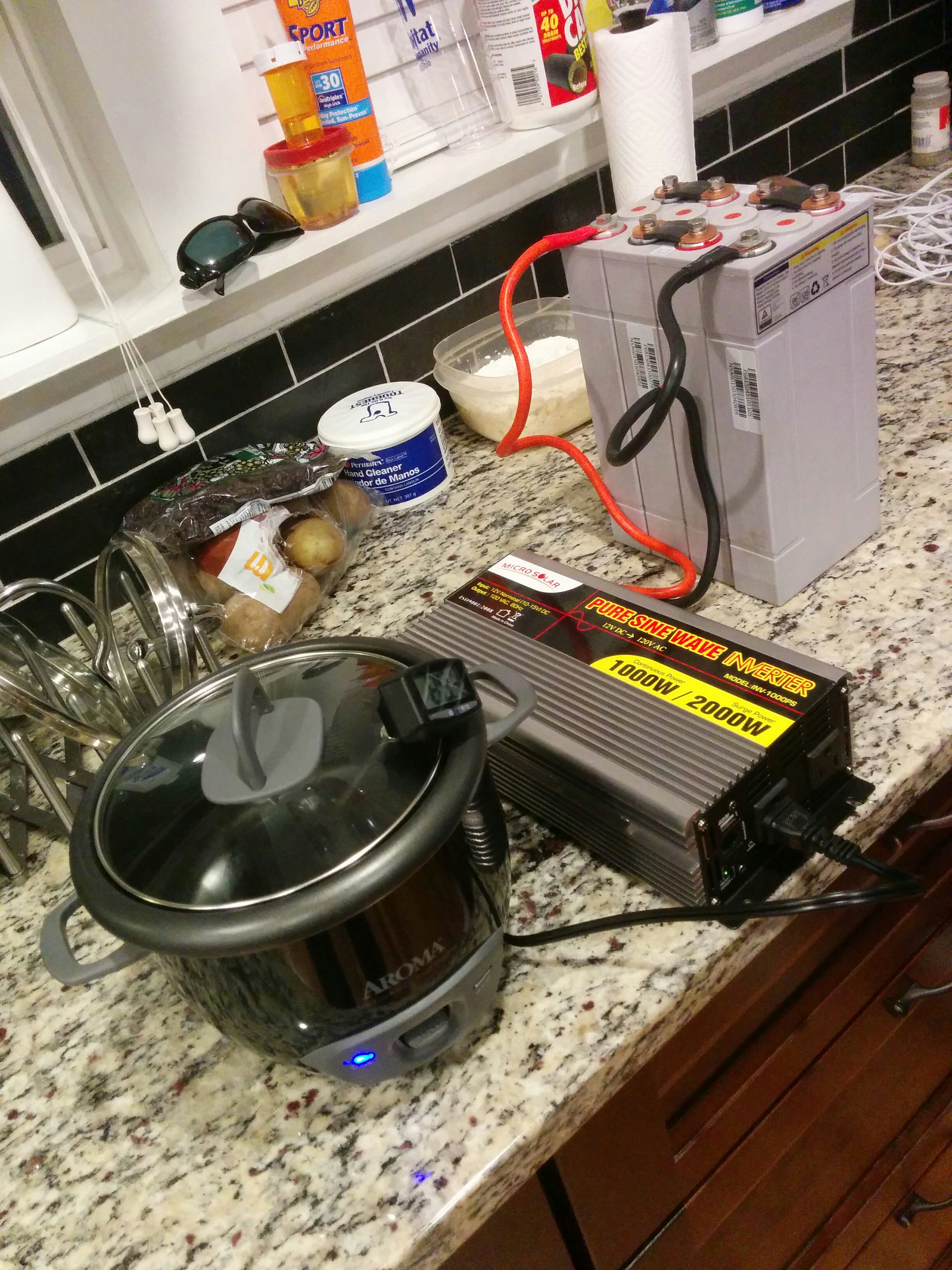
These kinds of batteries have metal connectors (busbars) that screw into the battery terminals. By joining them in series, your 4 cells x 3.2 volts = a 12.8V battery pack.
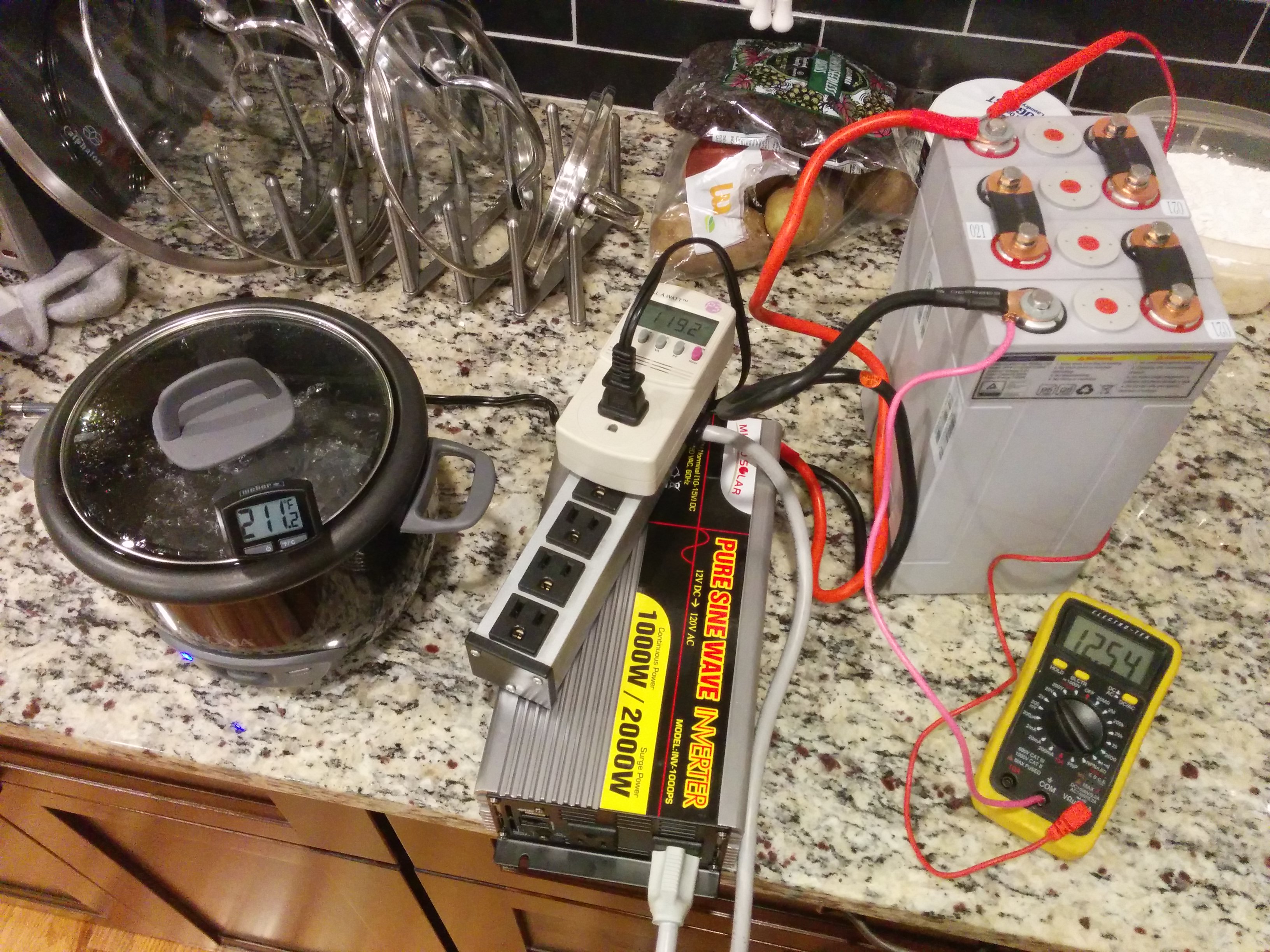
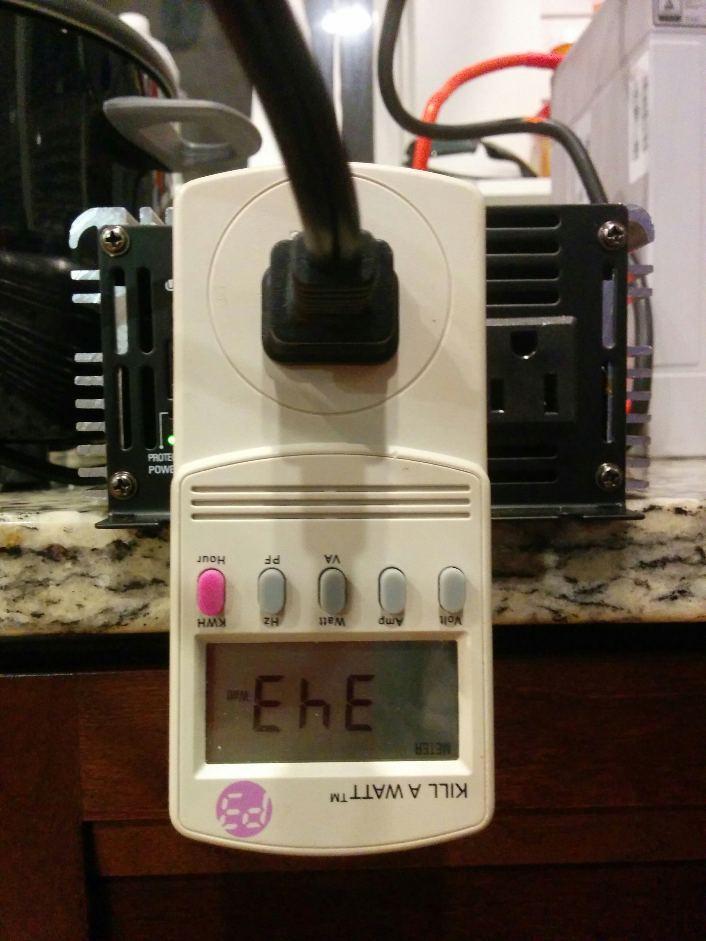
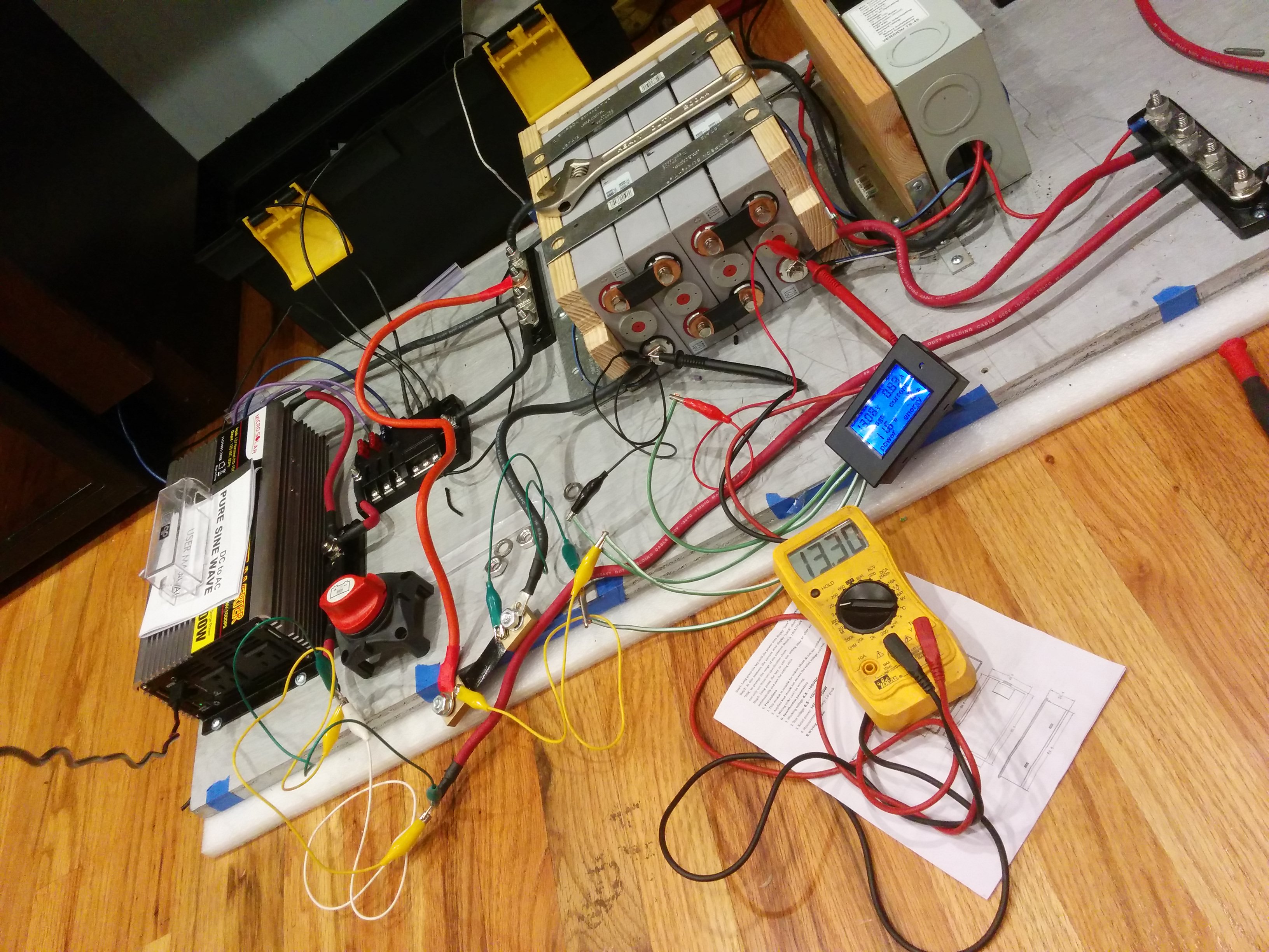
The red and black wires connect to the back of the inverter, which has posts you can screw the cable lugs down to. The front of the inverter has a standard household outlet. My first idea to test the inverter was to use my rice cooker, which wasn’t too extreme of an appliance (~350W). If the water got hot, then the inverter must be working. I put a thermometer in to see if it was doing anything. It was!
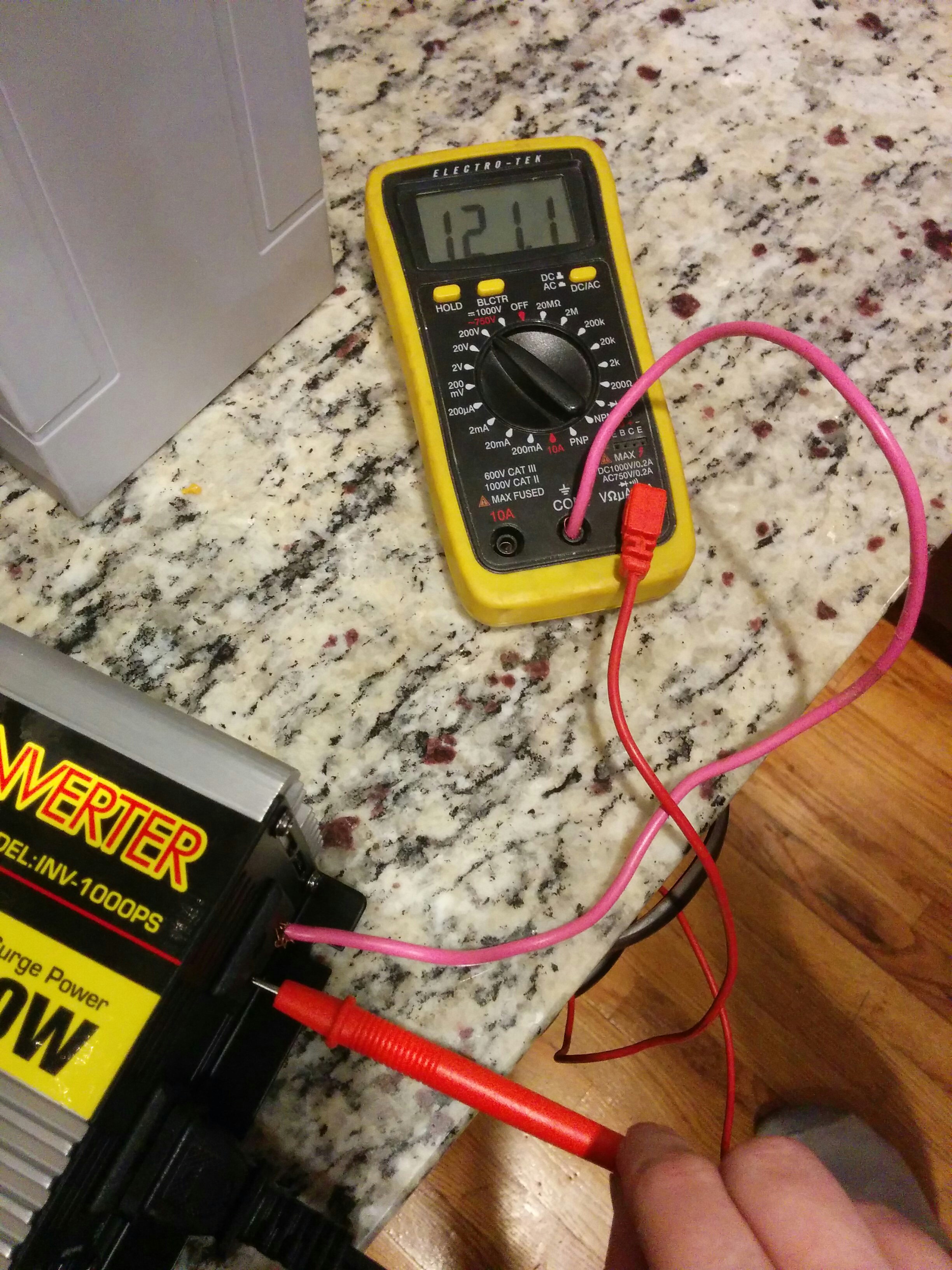
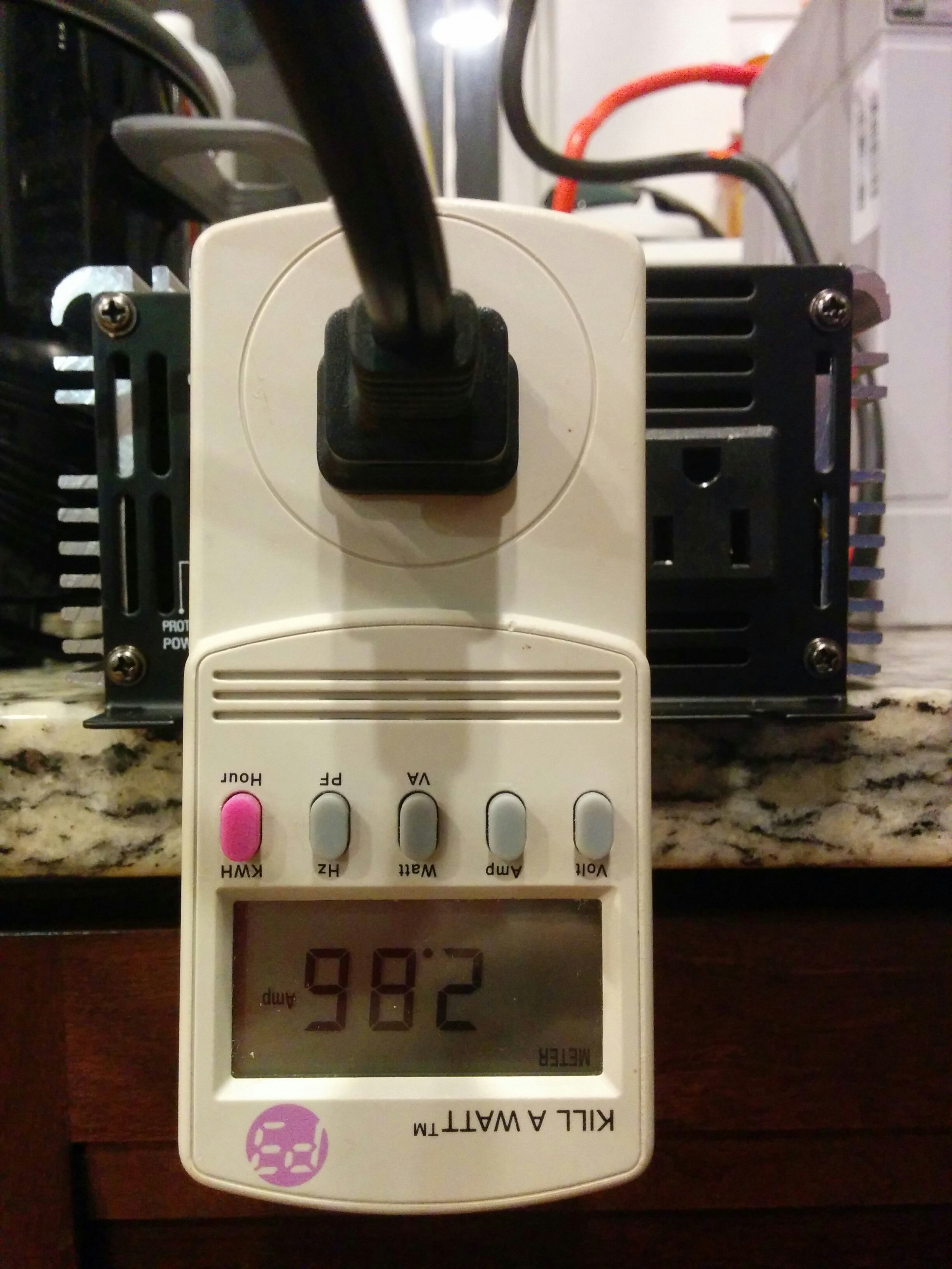
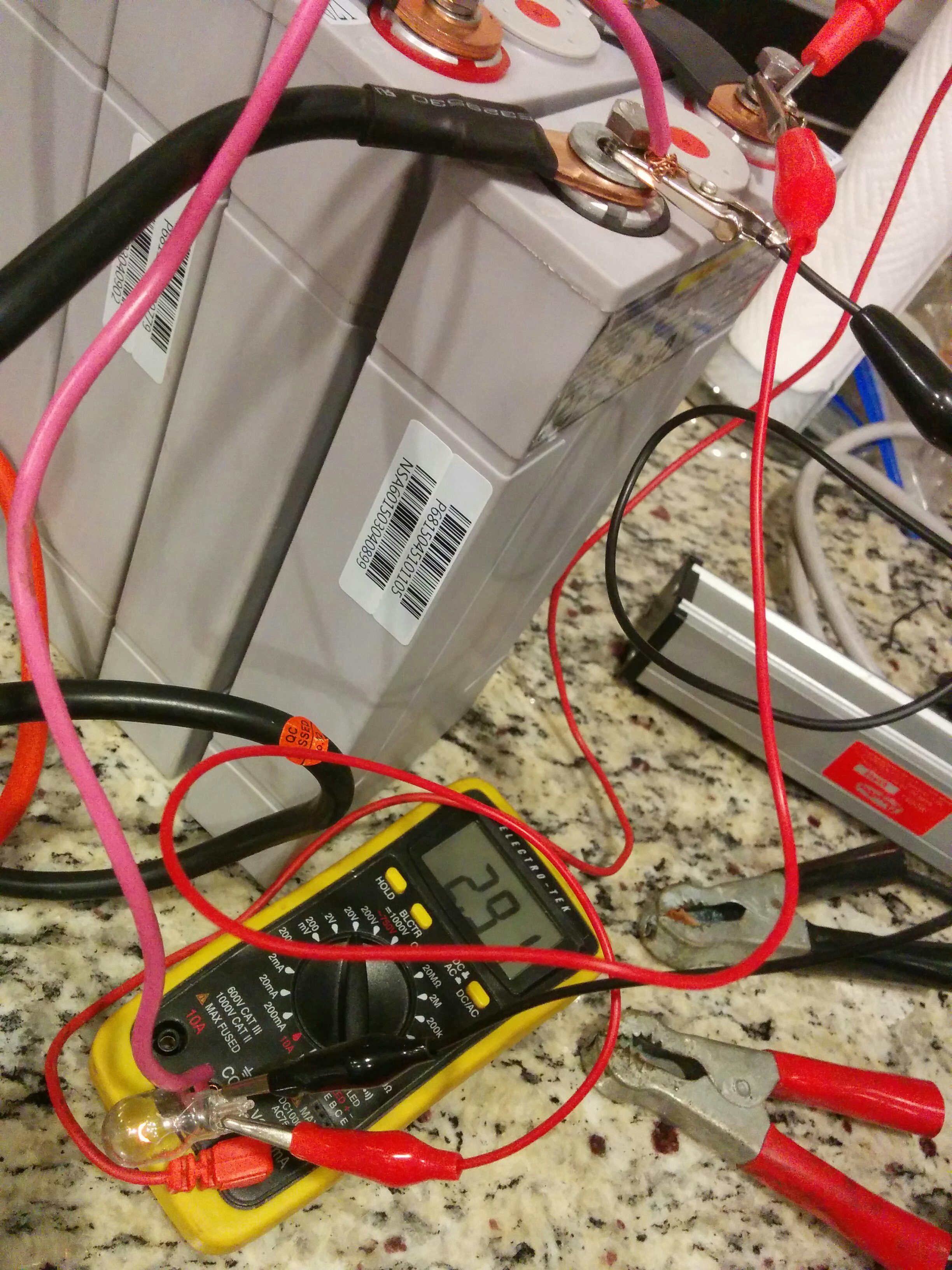
While I could check the voltage with a multimeter, I wasn’t quite sure how to check the current. I was not super experienced with multimetering, but I knew that measuring amps with one requires current to flow through the device, and if it’s too much current, it’ll blow the fuse. 350w / 12v = 29amps, which was definitely more than the “10A” listed on the device. What do?
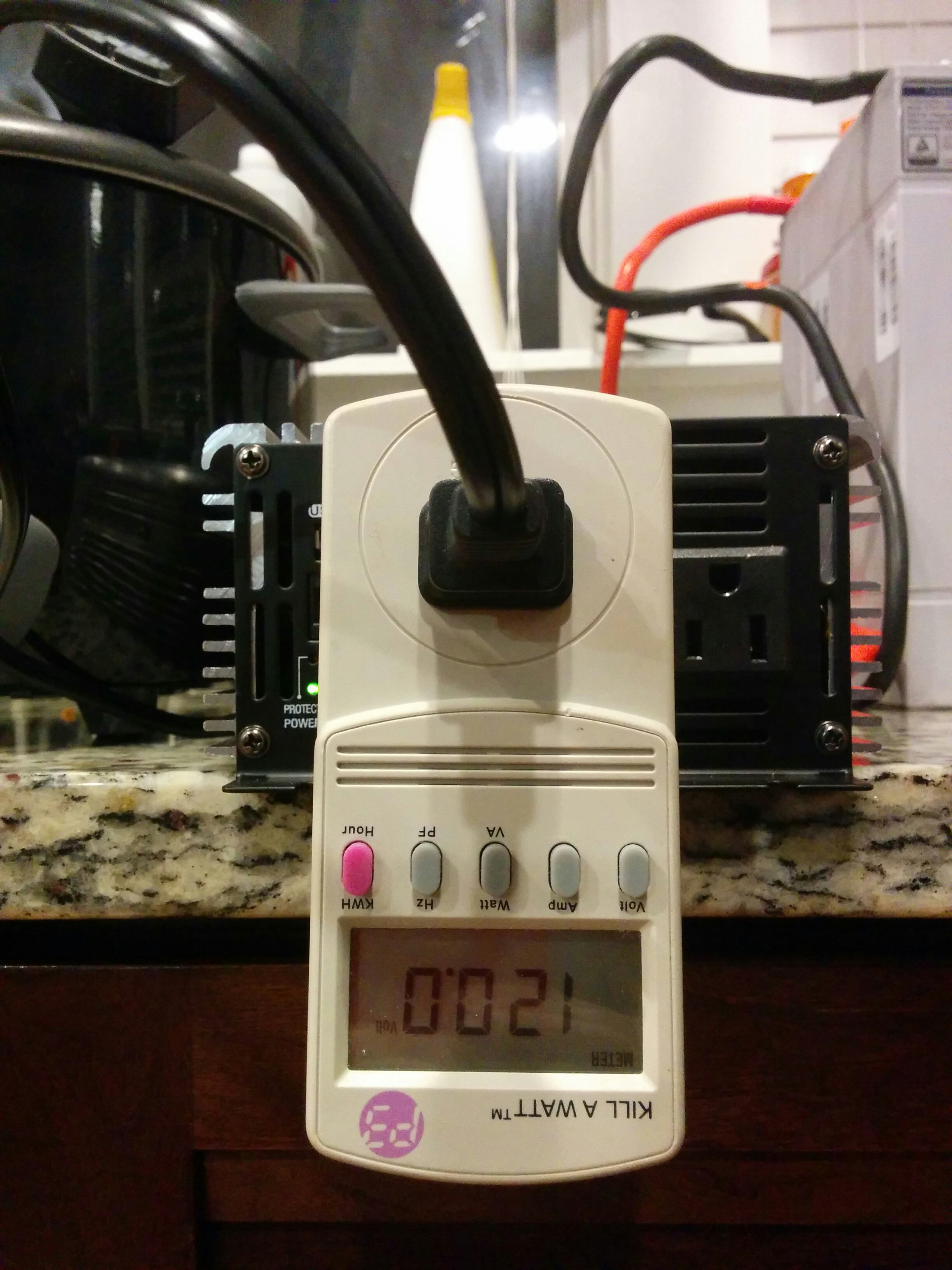
Garrett wandered by to see tf I was doing in his kitchen and upon hearing my situation helpfully handed me something called a “Killawatt.” I’d never seen one before but immediately appreciated its utility.
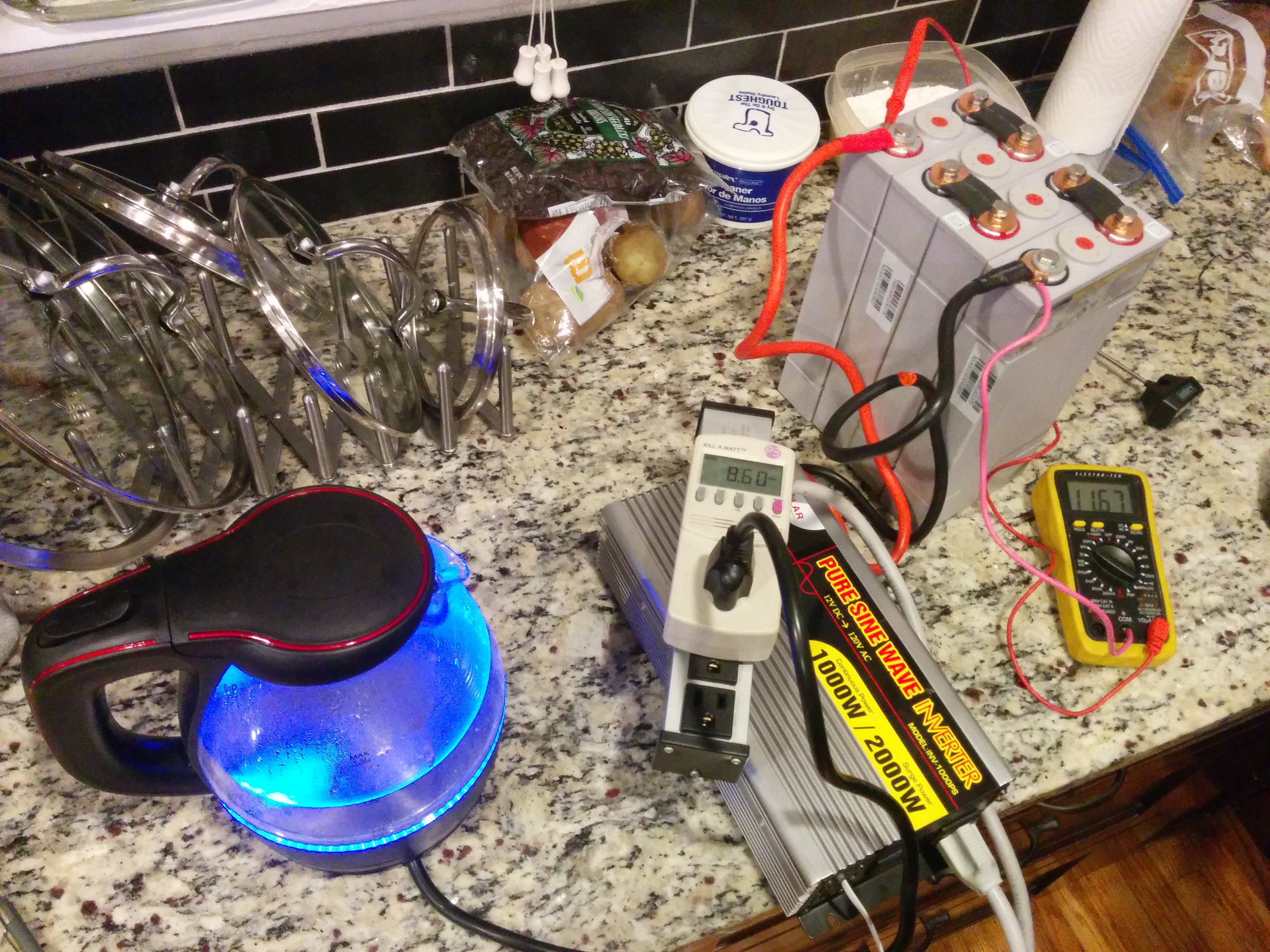
Now it was time for the real load test: the 1KW water kettle.
Everything worked great. It would have been nice to have a bit more overhead with the inverter capacity, but the water kettle doesn’t run for very long anyway, just a few minutes at most.
I then proceeded to bottom balance my cells by individually draining each cell down to a specific low voltage.
Upon seeing my battery delivery, Garrett volunteered up something called a trickle charger for cars that plugged into the wall and had a lot of options for carefully/slowly charging 12Vish batteries. After “bottom balancing,” I used this trickle charger to charge the rejoined pack up to full-ish again to keep them shelf-stable until I could attach them to the solar panels.
Building the Power Shelf
There was a sort of ceiling pocket formed between the remnants of the original metal van roof and the conversion company’s fiberglass roof. This seemed like an ideal place to tuck away a battery system. The cut off chunk of plywood left over from the bedframe even fit perfectly in this slot.
I would screw everything down to this “power shelf” before inserting it in the van. That way I could pull the power shelf out to work on it if I ever needed to, but as a default it would remain completely out of the way of the living space below. Also, rather critically, this was the most waterproof section of the entire van. At this point it was practically the only place in the van that I never seen any leaks at all.
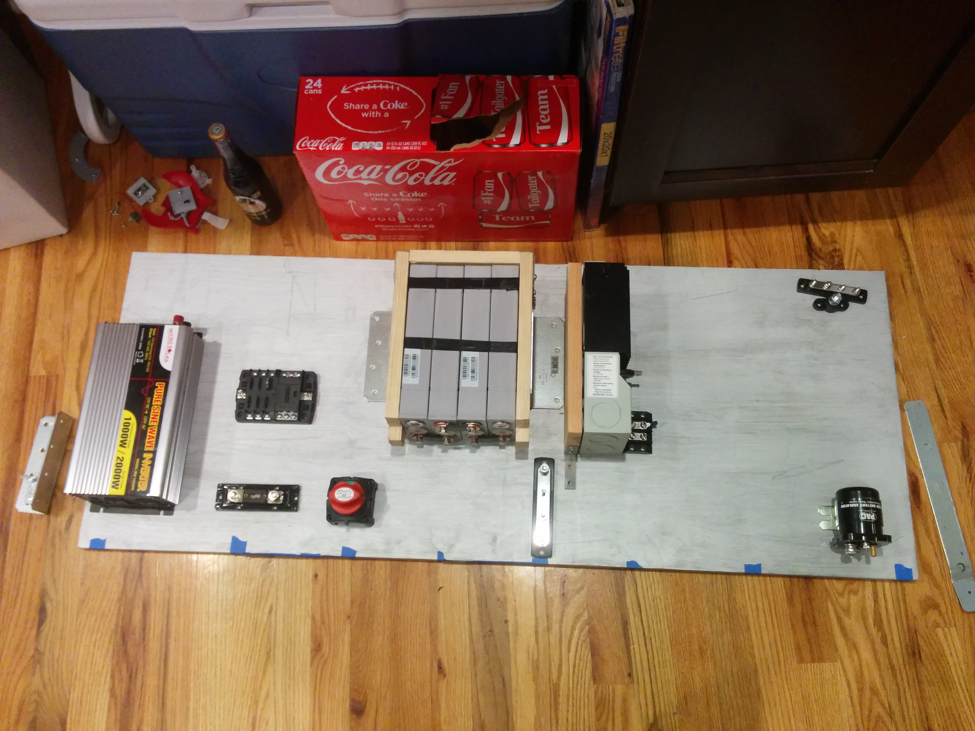
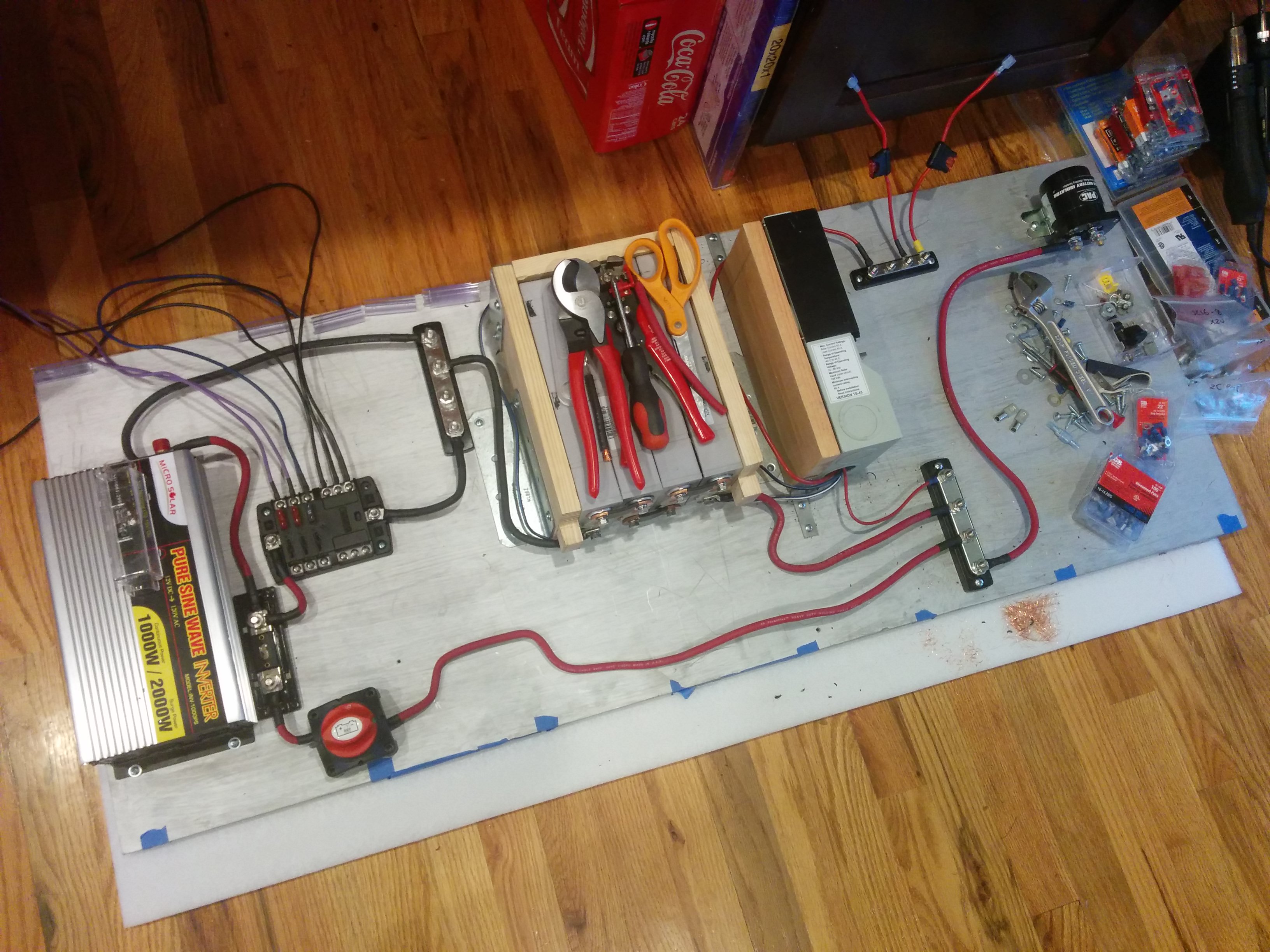
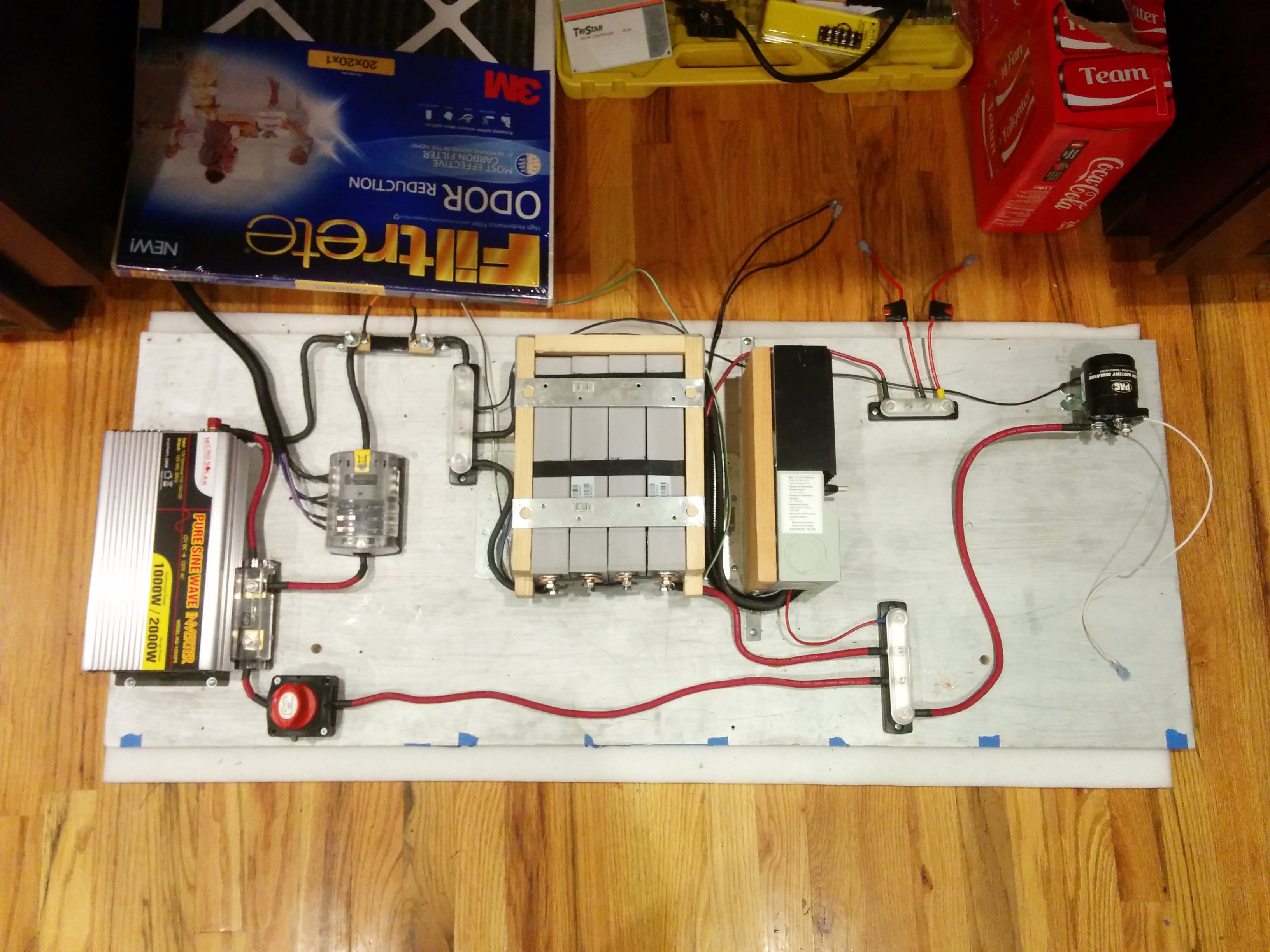
I painted the leftover bed plywood chunk in silver to match the interior and then began laying out my components. To the right of the battery pack is the solar charge controller, mounted on its side so that the serial connector would still be accessible post-install. On the bottom right is a massive solenoid/battery isolator that would connect to the alternator upon command. Down on the bottom left is an emergency disconnect switch and a fuse. I made braces and mounts out of scrap wood to mount things that needed to be contained on three sides (like the batteries) or mounted at a 90 degree angle (the charge controller).
The general idea: power would come in from the right, either from the sun (via solar charge controller) or the alternator (if the battery isolator was switched on). From the common positive with battery, current would have to pass through both a disconnect switch and a fuse before splitting between a 120V AC output and a 12V DC output. The 120V output would optionally let me use my more demanding appliances (laptop charger, rice cooker, electric kettle, printer) when I turned the inverter on whereas the 12V outlet would have 24/7 power for phone charging and interior lighting.
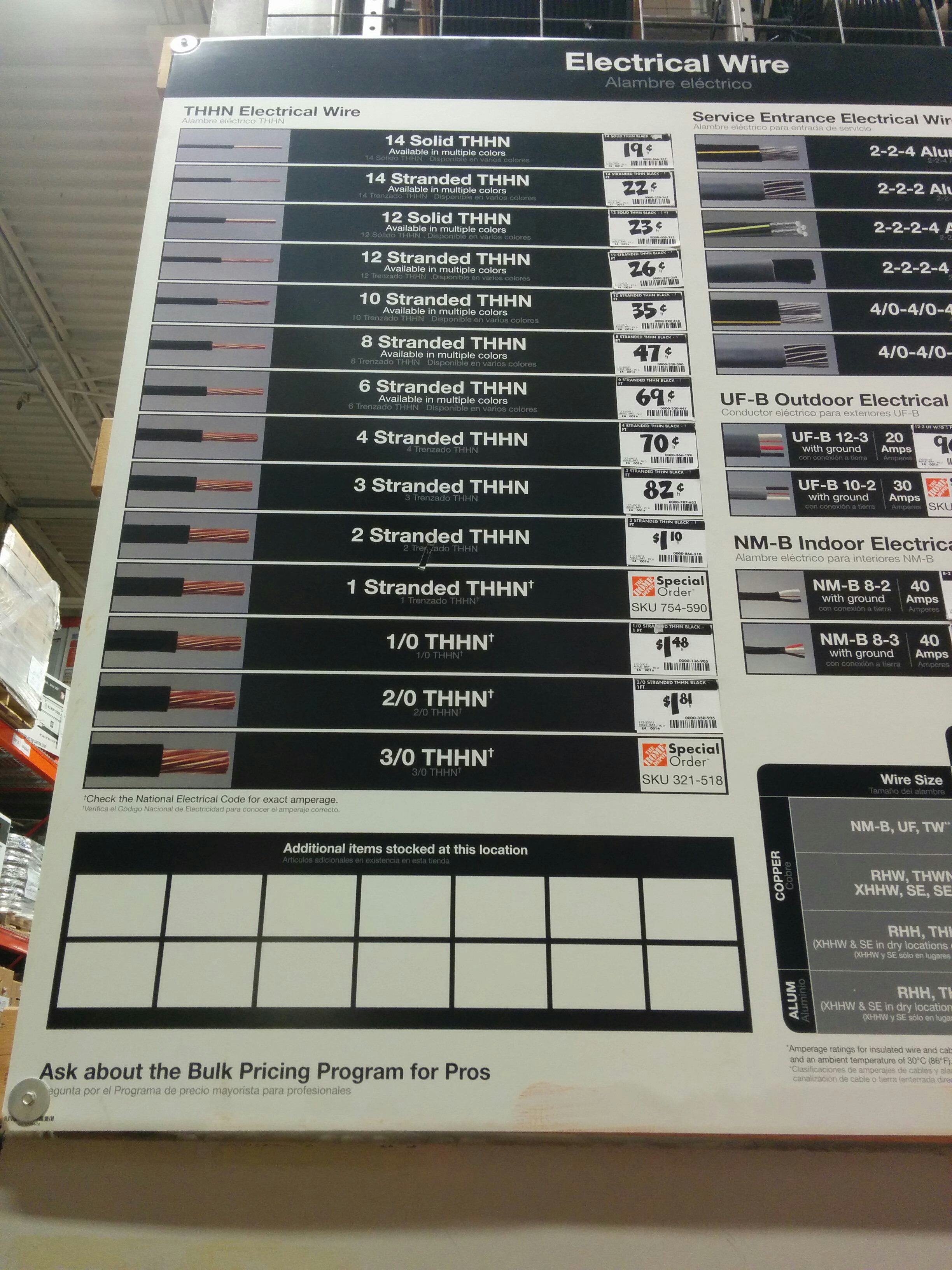
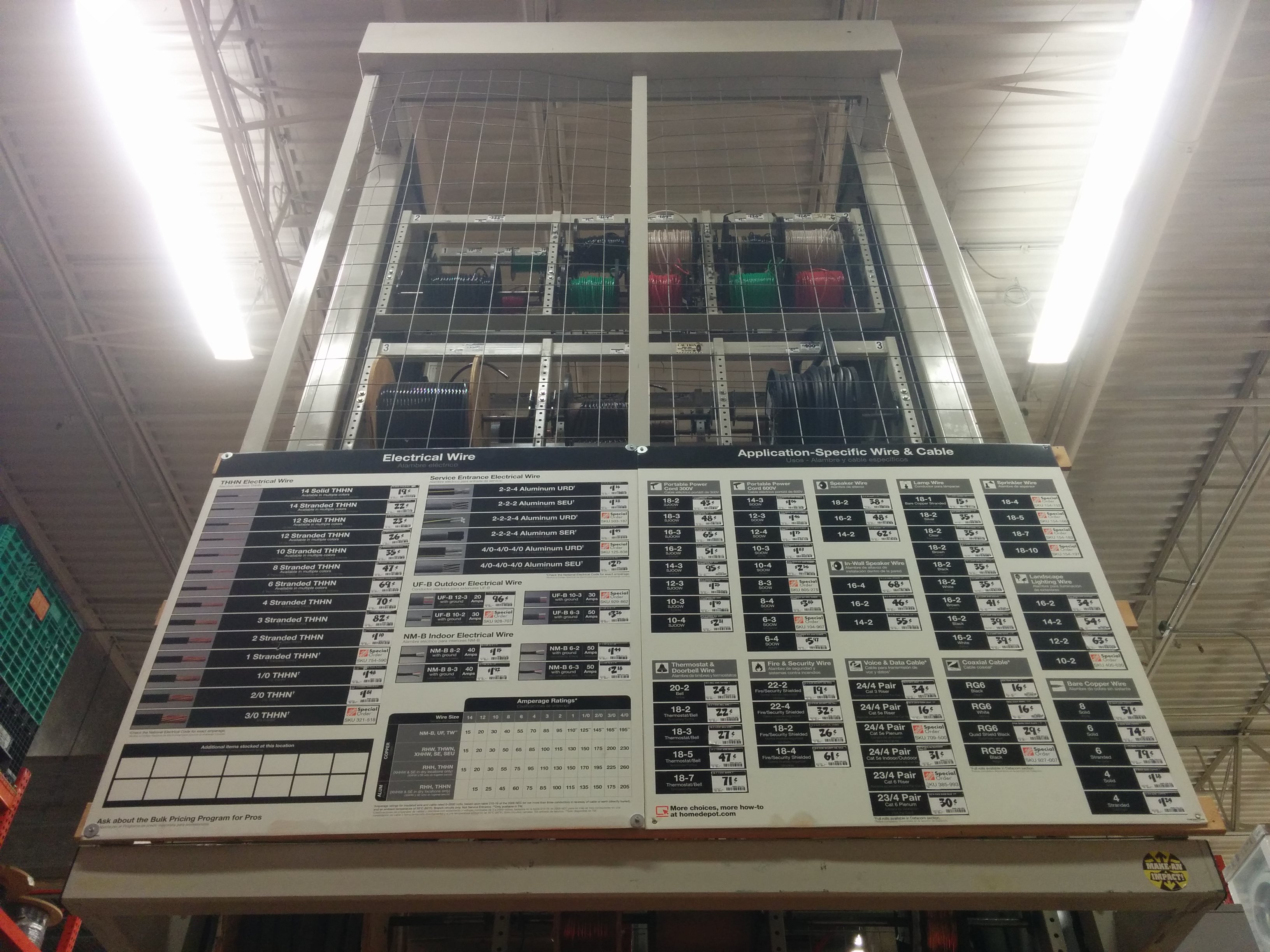
Now, I would need to wire everything up. My existing collection of cable, while plentiful, did not have a sufficiently chonky cable for some of my higher-powered shelf connections. Off to Home Depot…
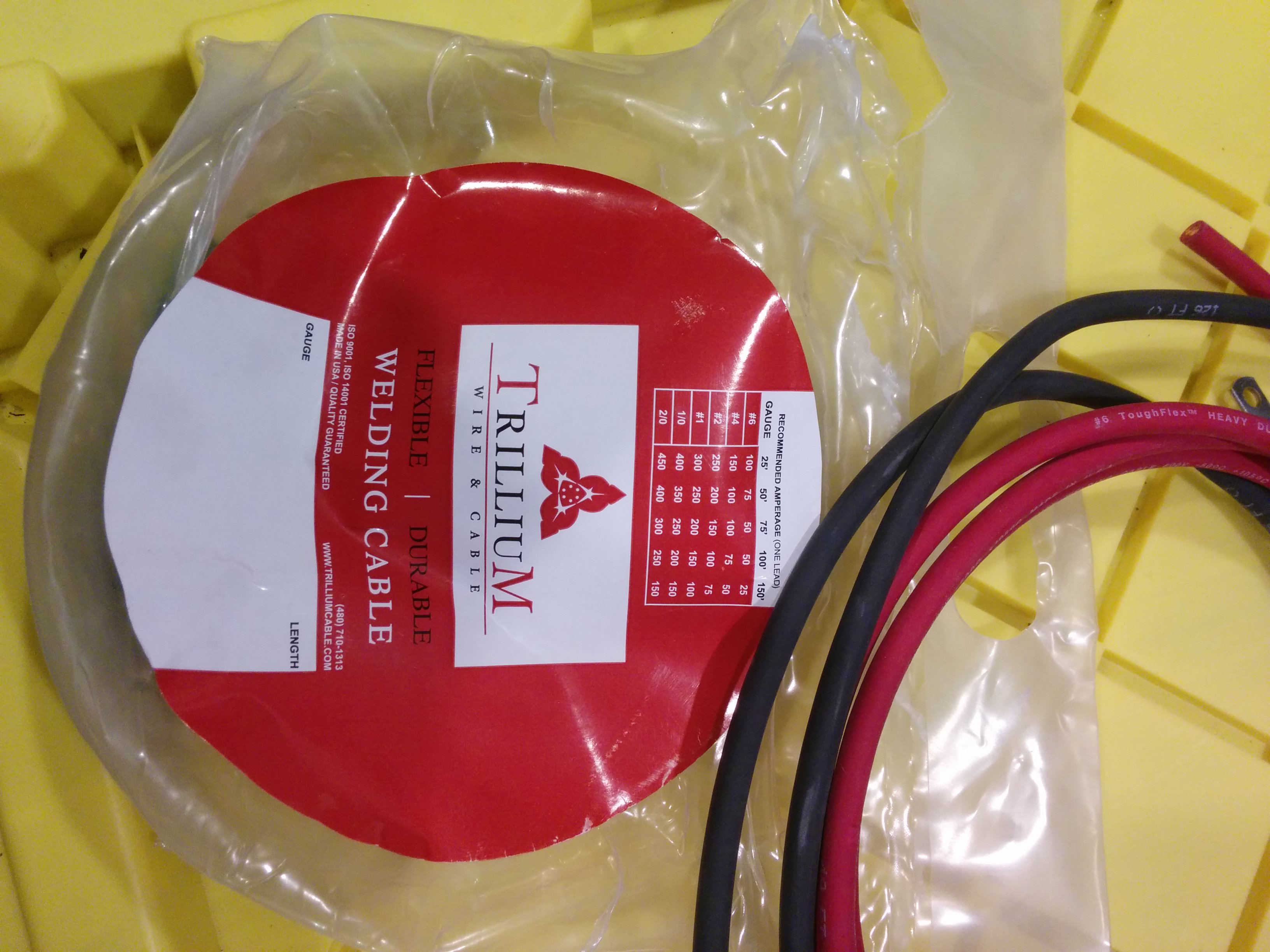
Well, I bought some of that THHN stuff, and it was so incredibly awful, I could barely bend it at all. I wound up buying something called welding cable instead. It was everything the THHN wasn’t: soft, supple, and pleasant.
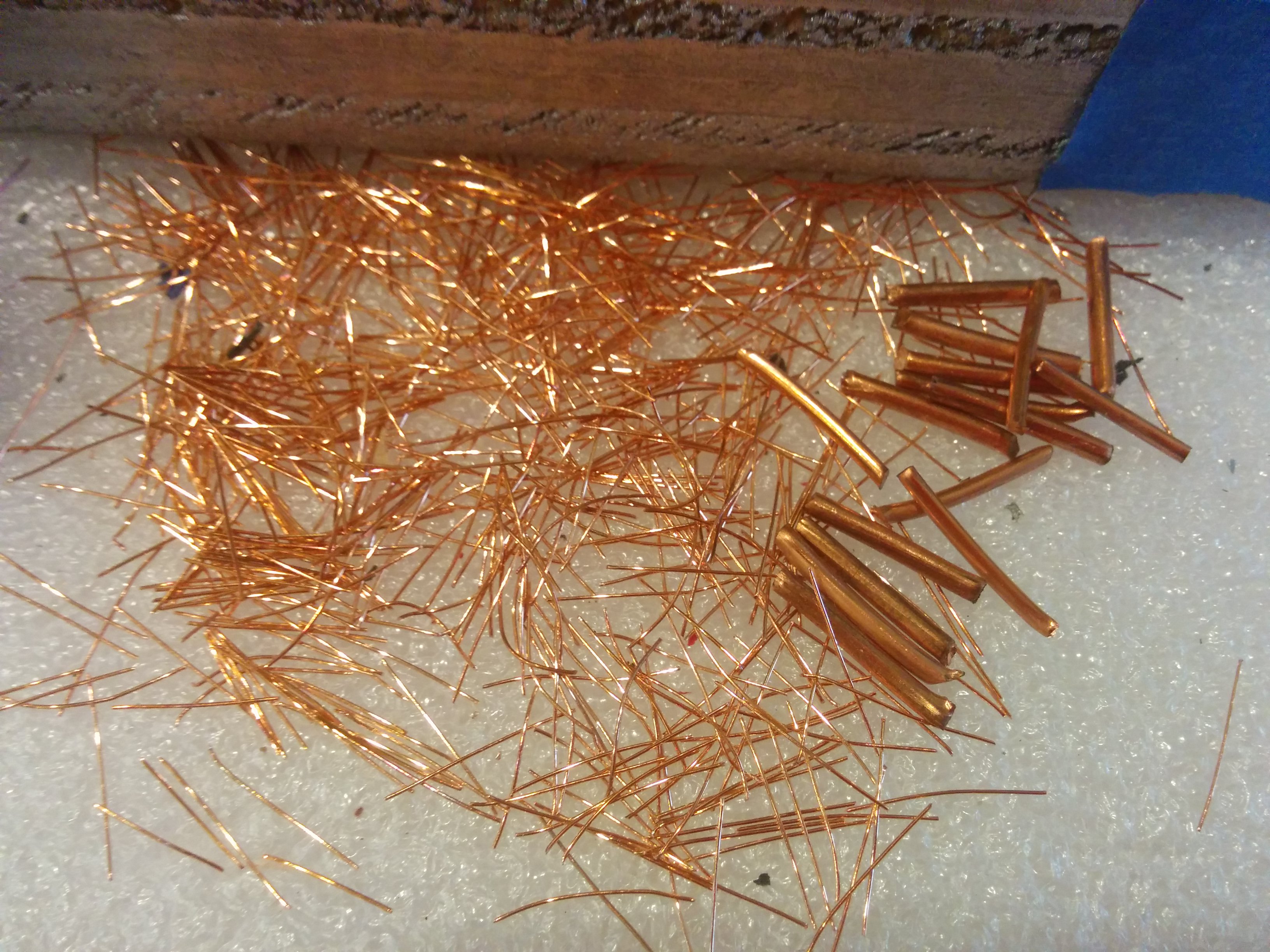
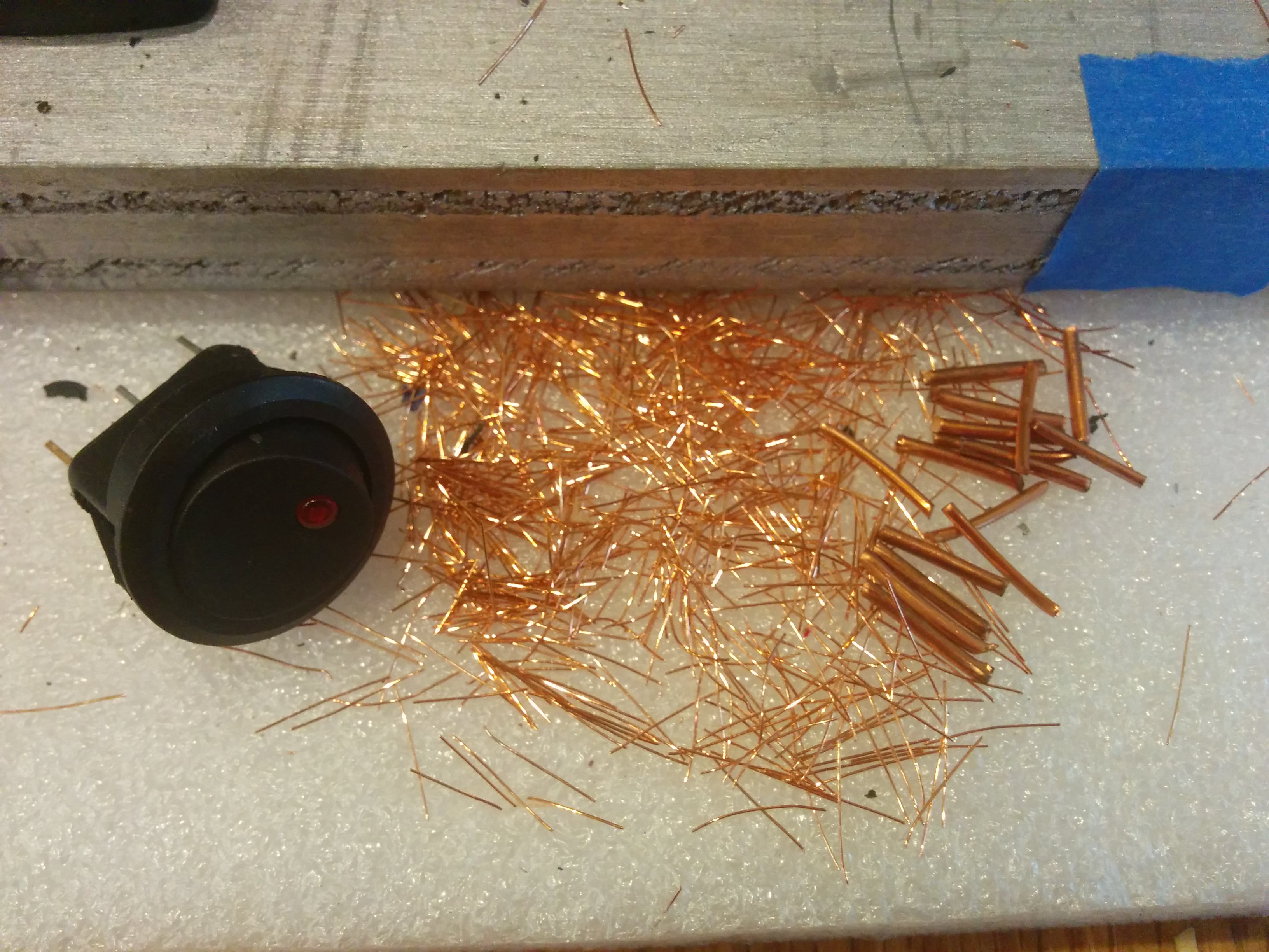
You can see the difference between the copper strands here. The welding cable is much finer.
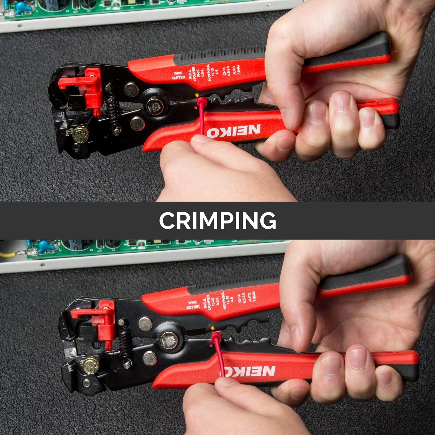
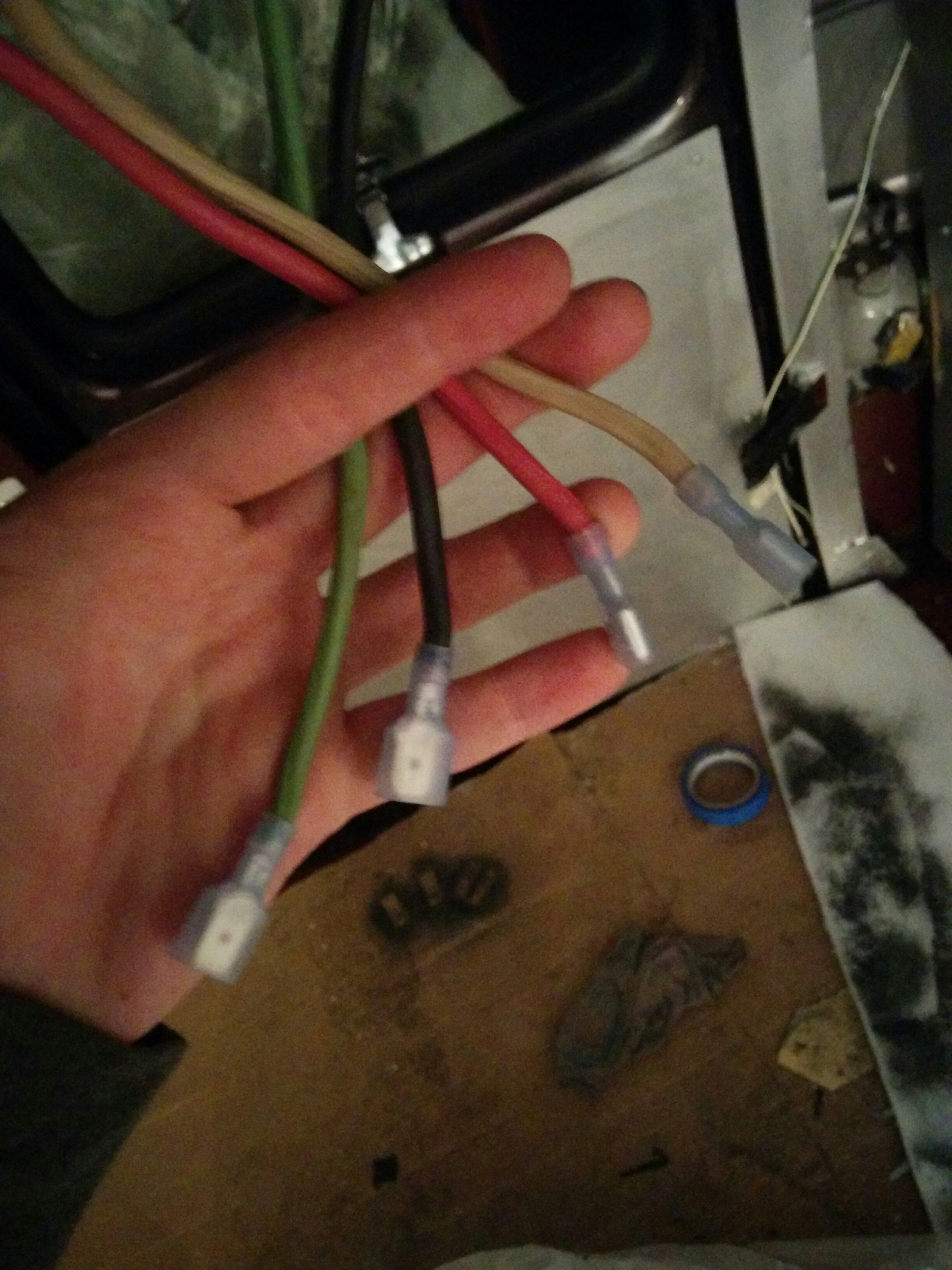
Once I had a collection of vaguely appropriately sized wires, I needed some way to turn it into cables I could actually connect to things. I’d seen a lot of these small auto connectors while taking apart the van, but I’d never attached one myself. I had an automatic wire stripper I’d gotten for making breadboard wires for the single EE lab I’d managed to afford thus far which also had a crimping function for the small connectors. Garrett showed me how to use them to crimp the connector terminals. I gave it a shot and the wire immediately fell out. He showed me again and his stayed on! WTF. You have to really hulk out on these things if you have low grip strength. I had to do a few for practice before I got the hang of it.
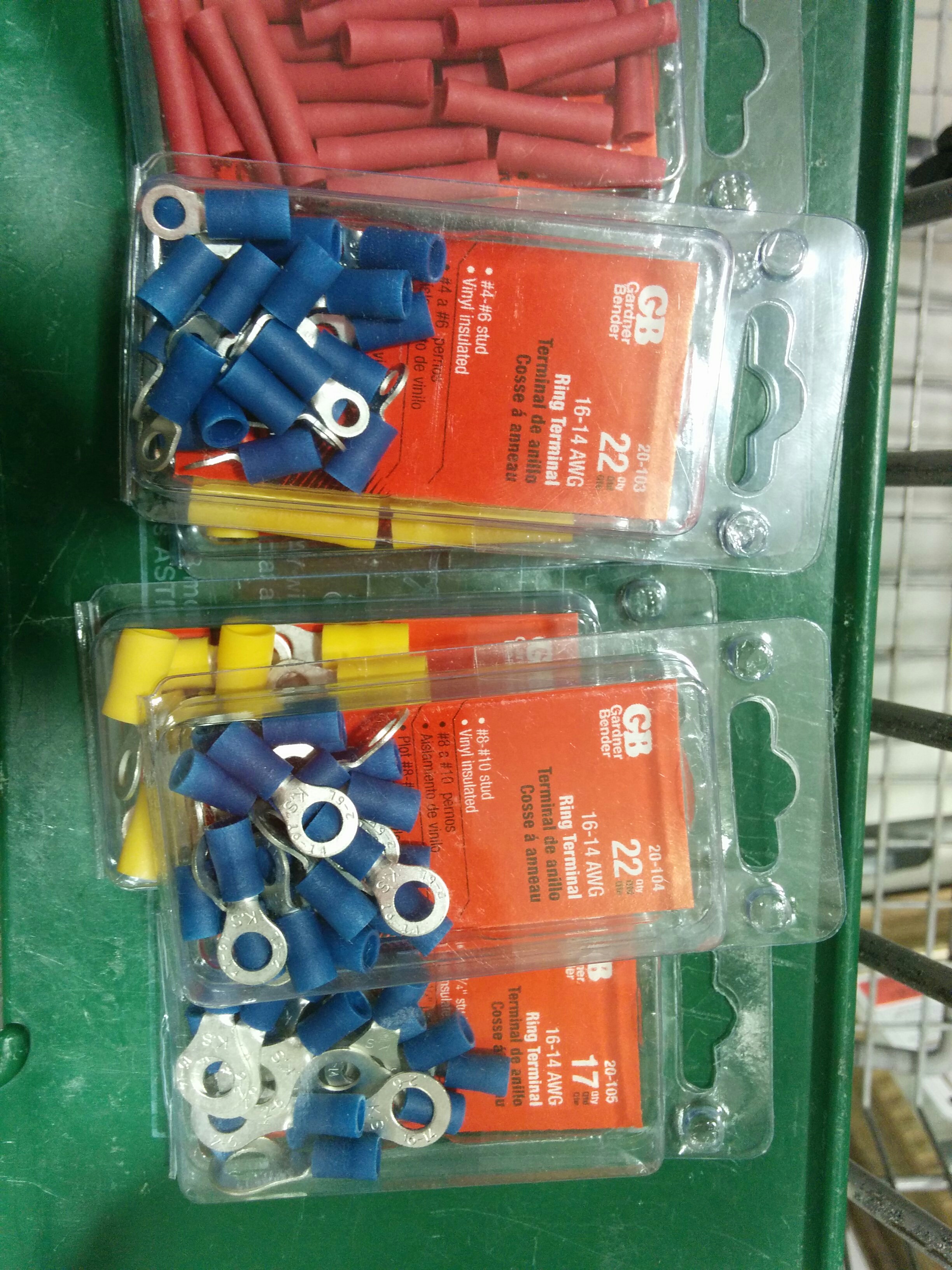
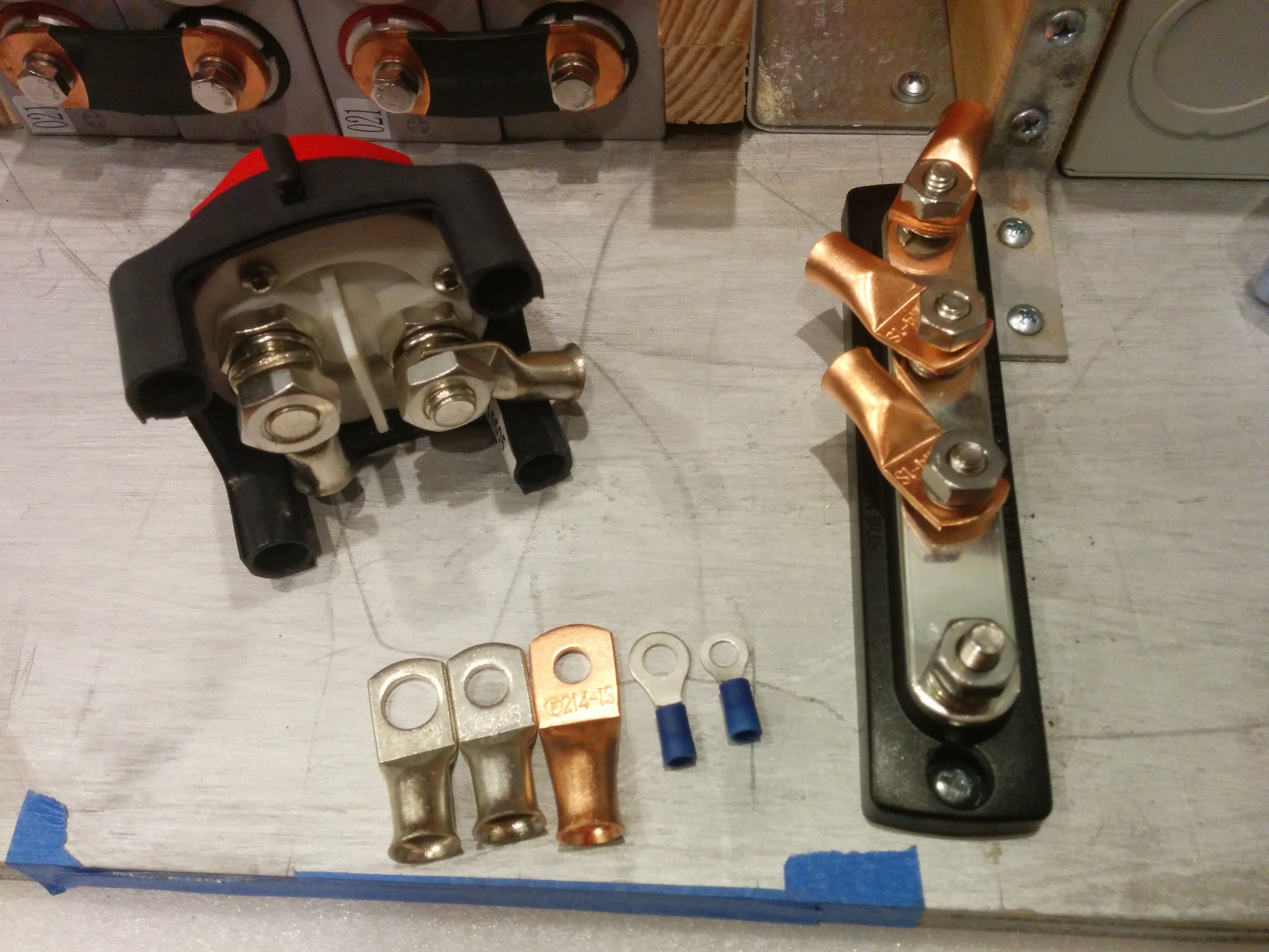
Figuring out what size wire I needed wasn’t too bad, but figuring out how to size my cable lugs took a while. Sometimes you have small wires and big wires that need to interact with the same post size. Also, different connectors can only accept a certain range of wires. I didn’t want to lose too much time and this was a blocking operation so I just got a bunch and returned the ones I ended up not using.
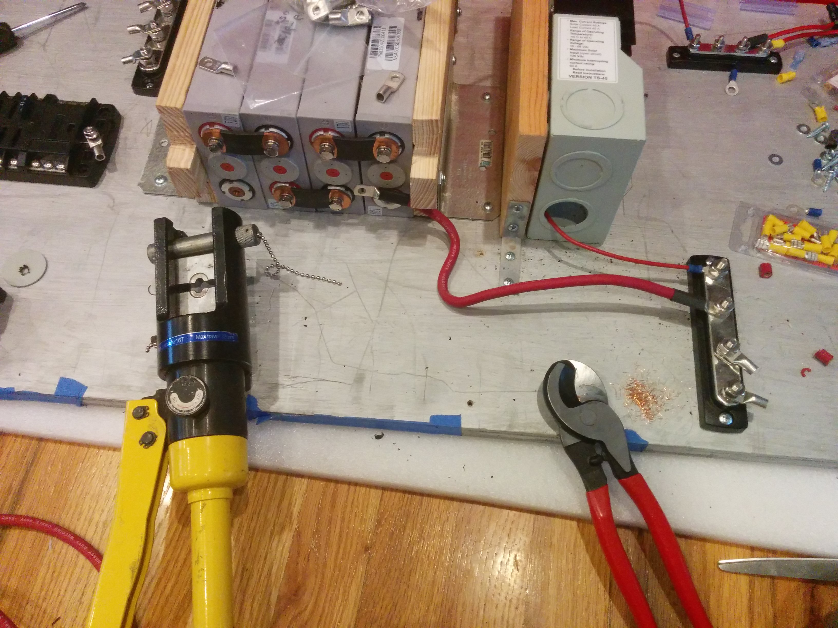
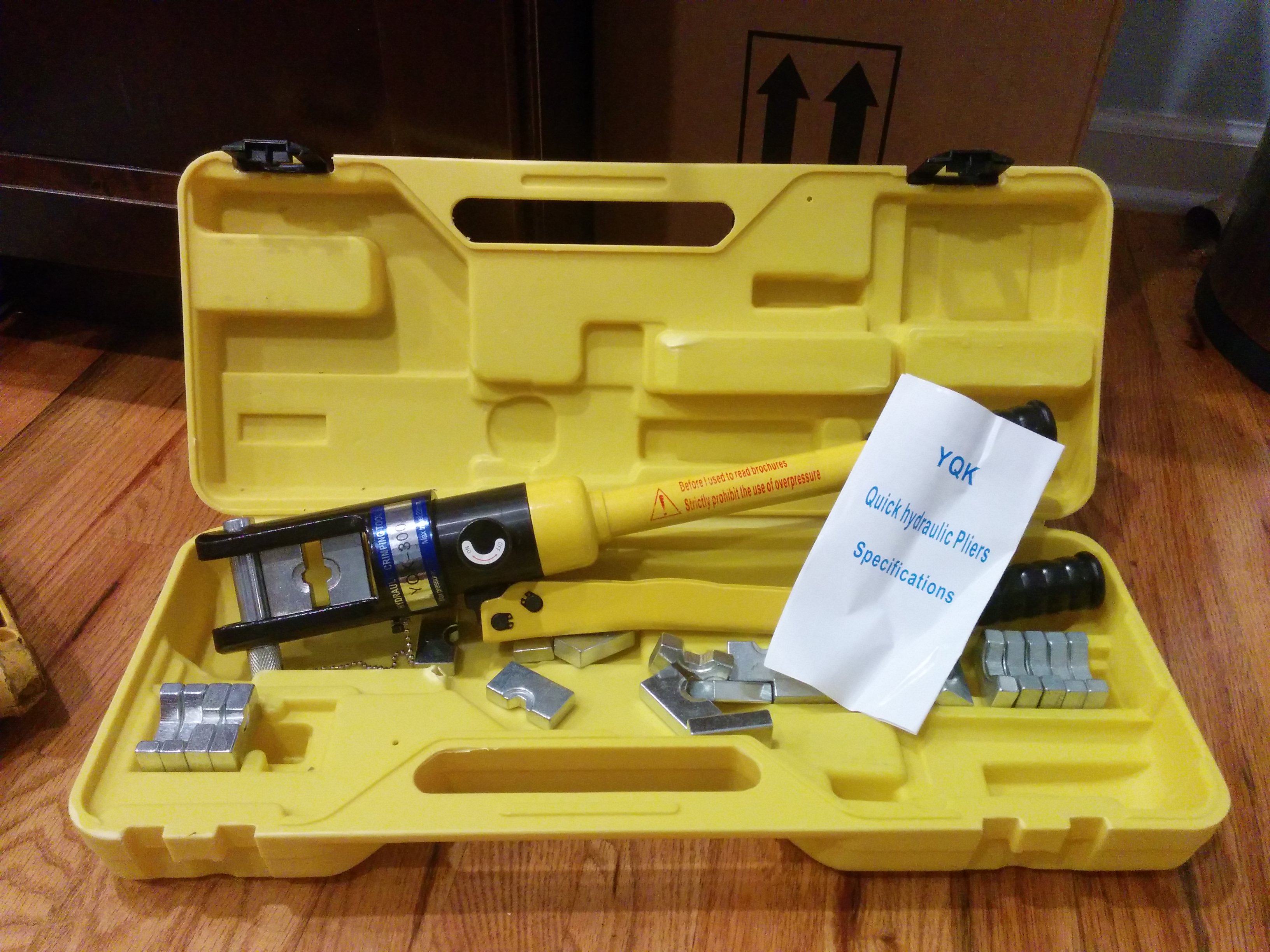
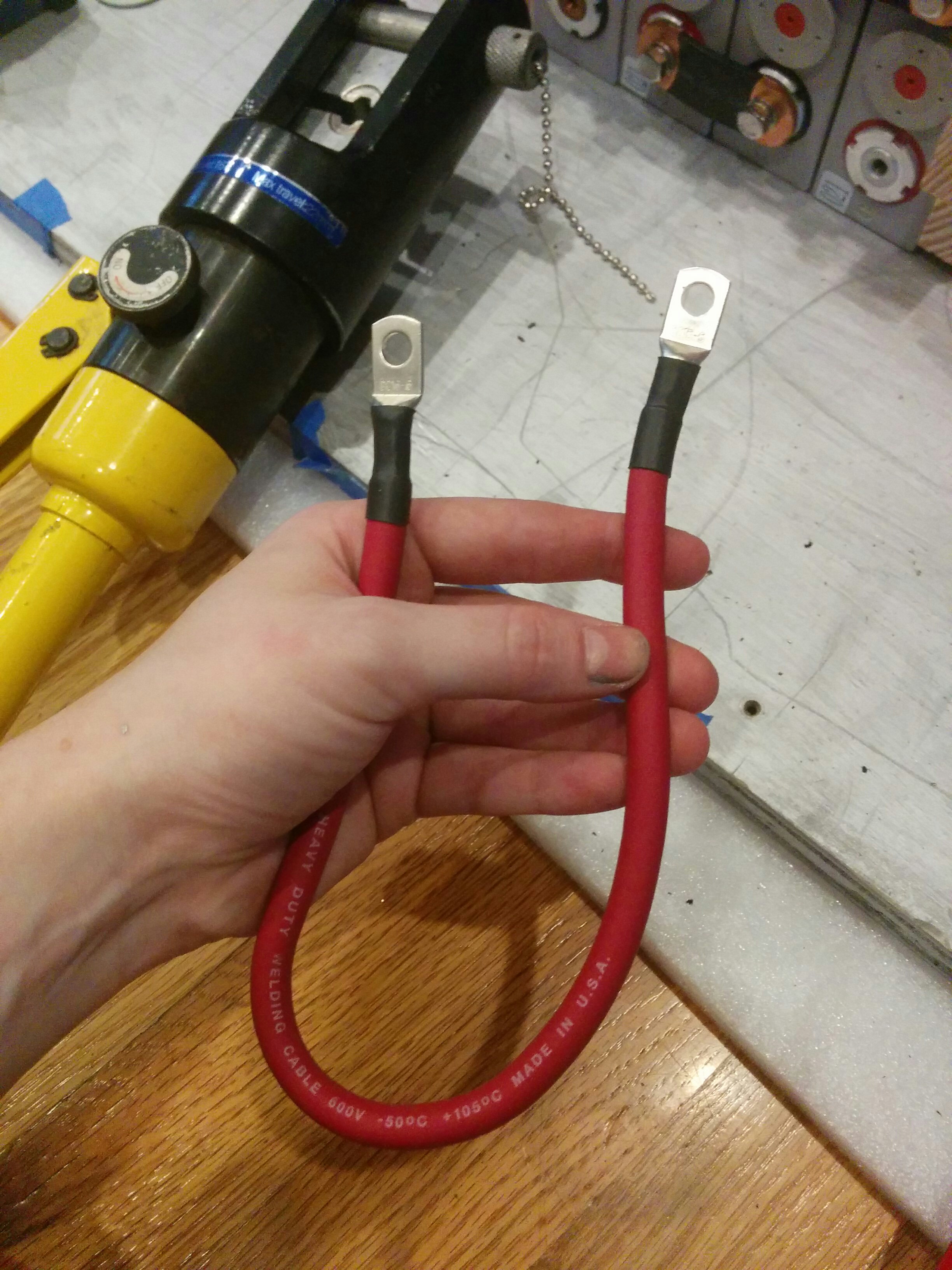
After a certain size, you ditch the smol hand crimping tool. I had seen Rob use some giant thing to add a lug to the 2/0 cable and a fuse in the front of the engine compartment. This mighty metal squisher was called a “hydraulic crimper.” You would insert a die and then hydraulize with the handles until your lug was squished. I actually found this a lot easier than the tiny hand held crimps.
I added a bit of heat shrink because I thought it looked nice.
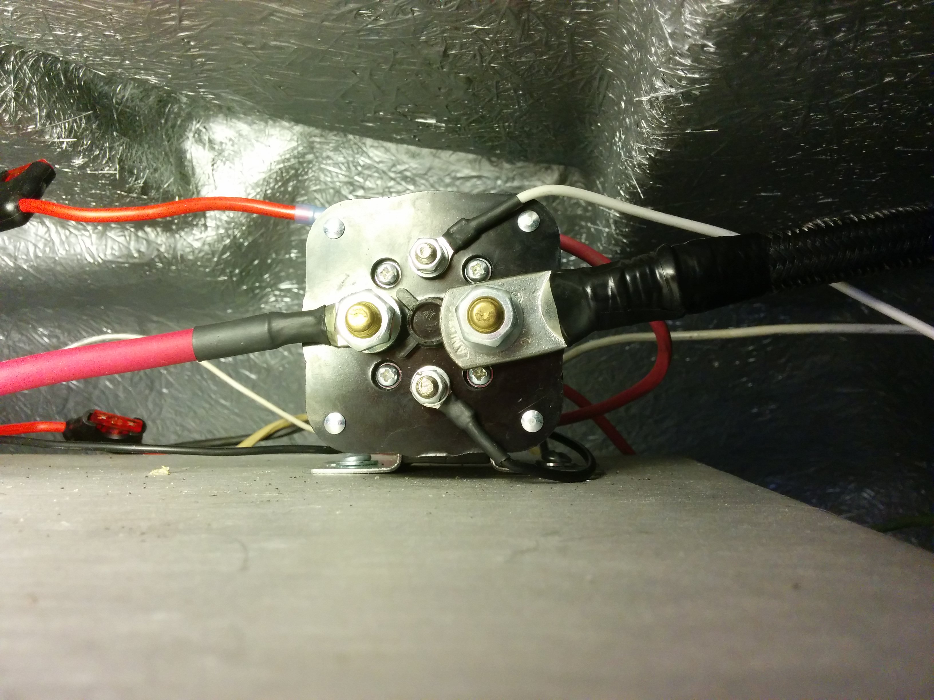
The 2/0 is too big for the post here. You can sort of squeak by adding a washer but it’s not ideal since the washer doesn’t connect current as well as a properly sized lug/mount would. The top and bottom posts are tiny because they don’t carry much current. They connect to the power switch near the steering wheel and toggle the solenoid on and off, enabling the power to flow in from the right. (I also had to ground my power shelf to the chassis for the return path for alternating, but I forgot to take a pic. -_-)
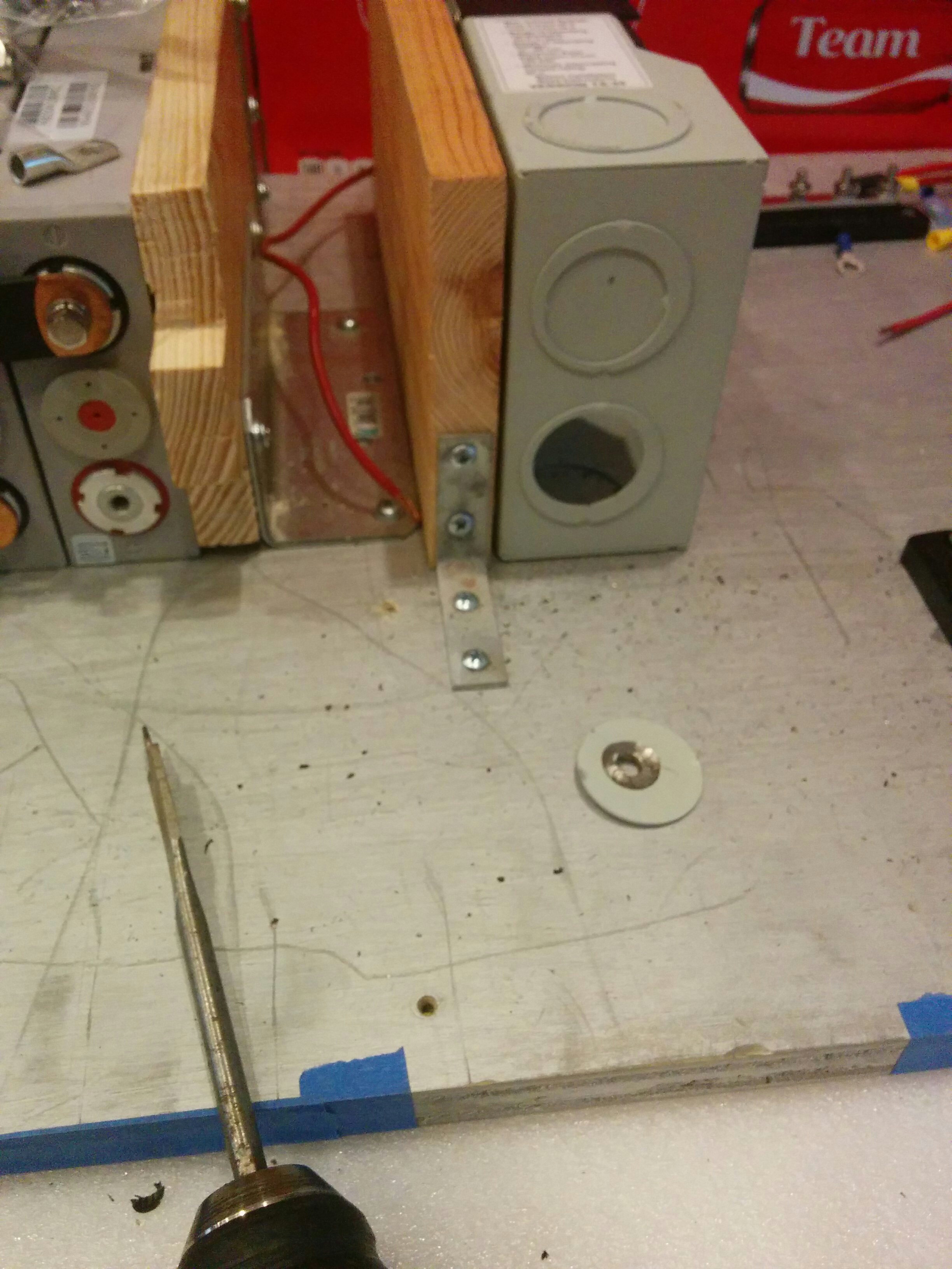
I had to take out this metal piece on the charge controller so my wires could pass through. I started drilling it but the whole segment was pre-perforated in some way that it easily popped off…
I was really paranoid about cutting these too short. I saved these connectors for after I’d done the power-shelf stuff since having a good connection to the solar panels was important.
I attached inline fuse holders to both solar panels on the power shelf connection side in case anything Went Wrong; you can see them on the top right tipped in blue (these connect to the blue connectors in the previous photo). I had to modify the cover for the giant fuse near the inverter by grinding an extra hole in its fuse cover so that the 12V DC output could split between its road to the inverter and the 12V fuse block.
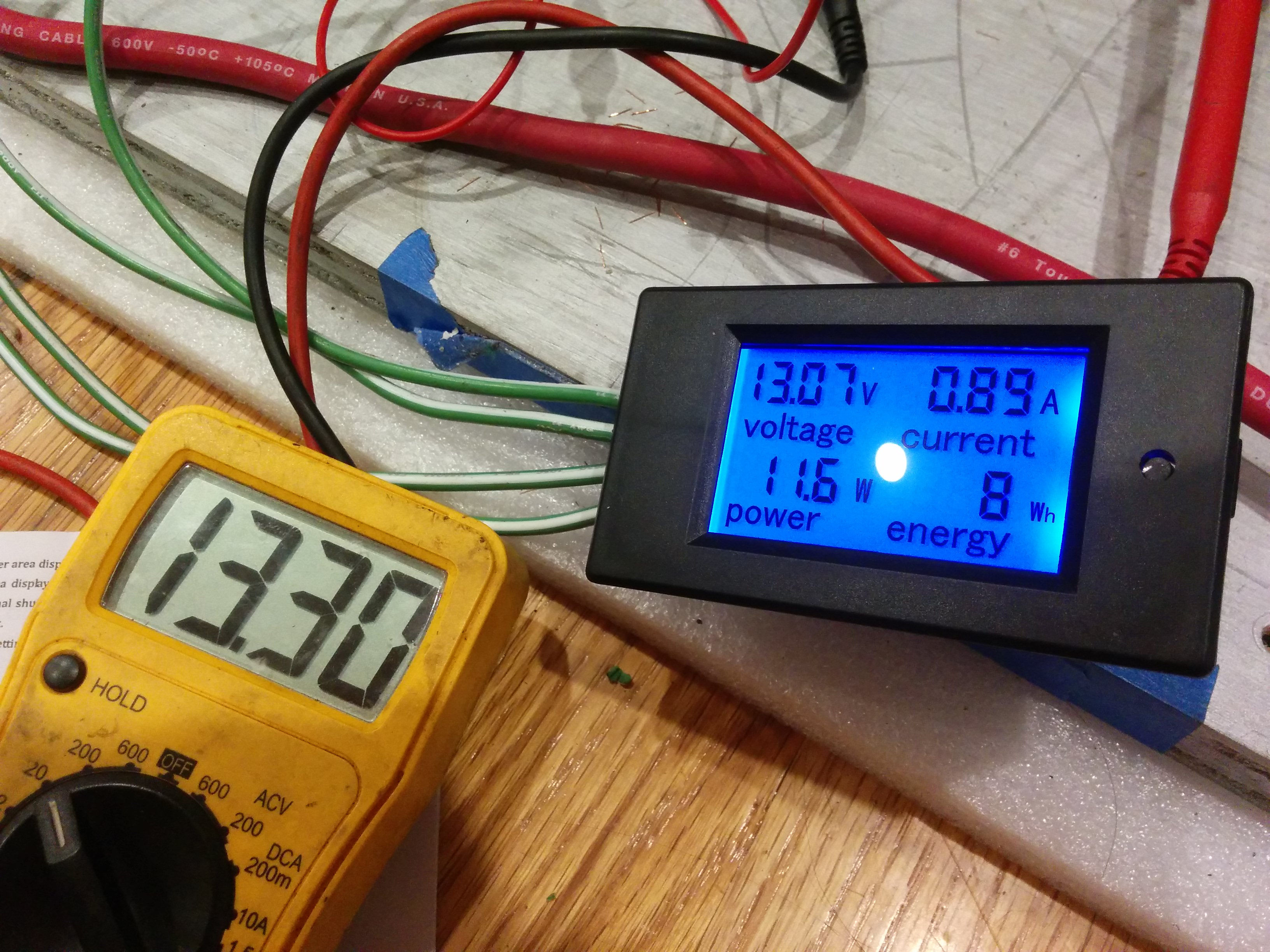
Testing the shunt for the ammeter display. The amount of additional wiring required for even the most basic of telemetry data is kind of insane.
I was a bit concerned about the ~0.23 difference but this was (upon some strategic wiggling) at least partially attributable to my hodge podge temporary connection scheme. (I had noticed something similar with the battery, but there again I had just wedged a raw wire end under a busbar since the negative lead was missing from Garrett’s multimeter, lol.) When things were properly installed the gap closed quite a lot, but there was still a small offset that I just mentally accomodated to over time. It would have been nice if the panel had some calibration functionality. I had my own multimeter in NY that I would reclaim upon my return which I used to keep an eye on things over the years.
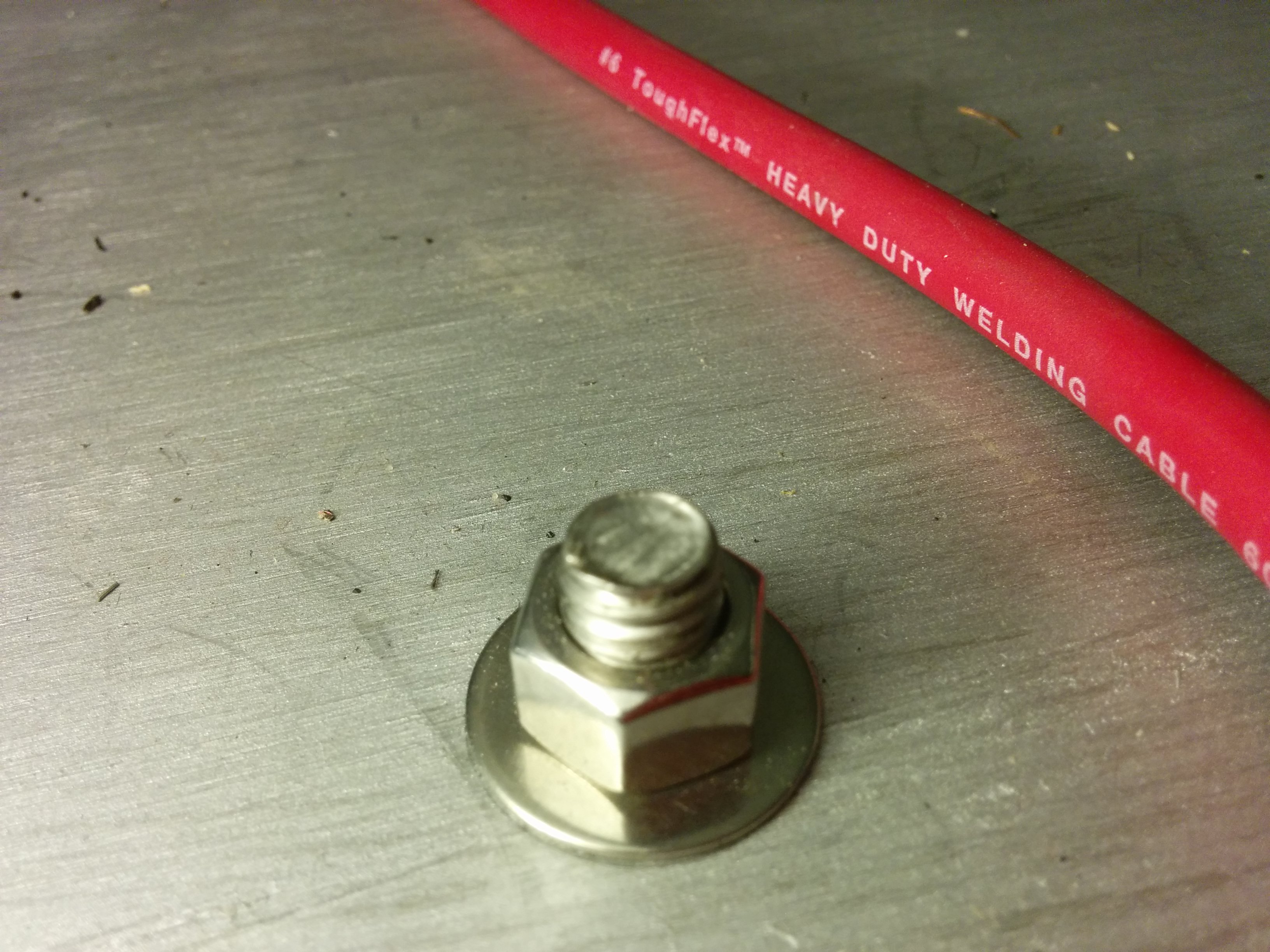
You can see that two holes have been drilled on the lower 1/3 of the board. This is where the shelf will attach to the van roof remnant.
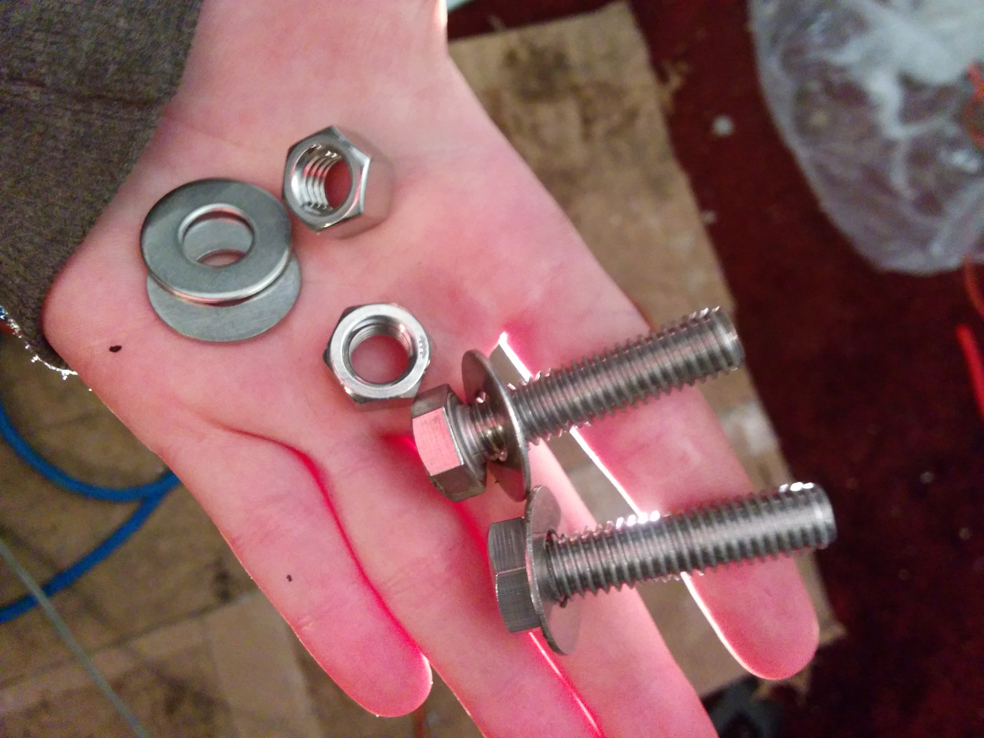
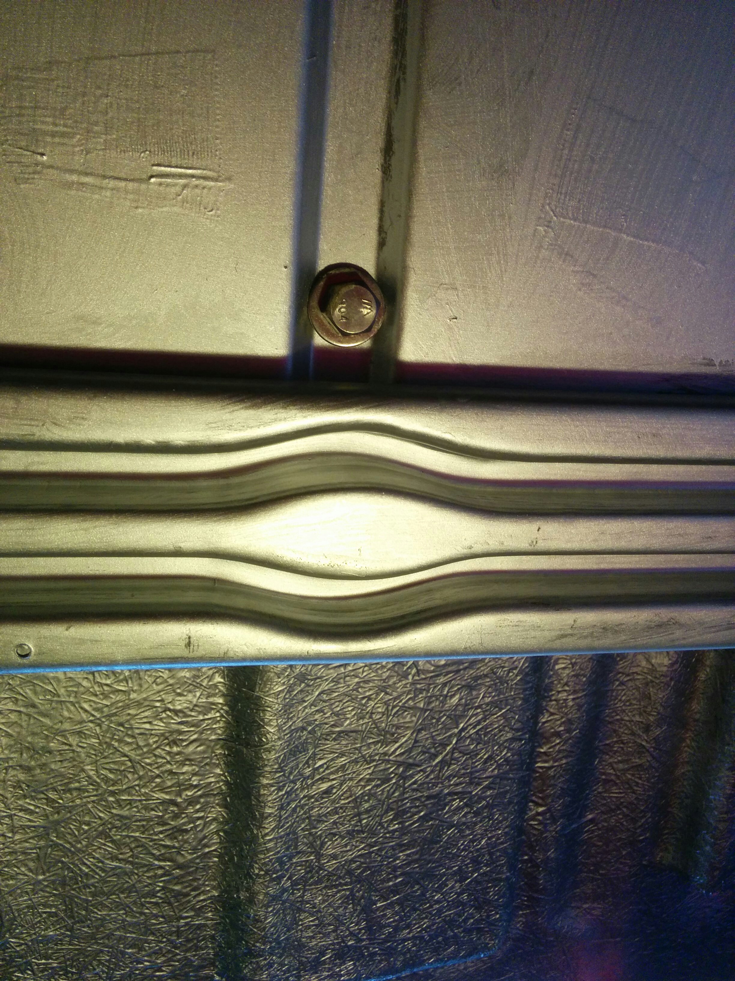
Bolts that attach the shelf to the van roof, and a view from below of the power shelf deck with the power shelf installed.
Room Lighting
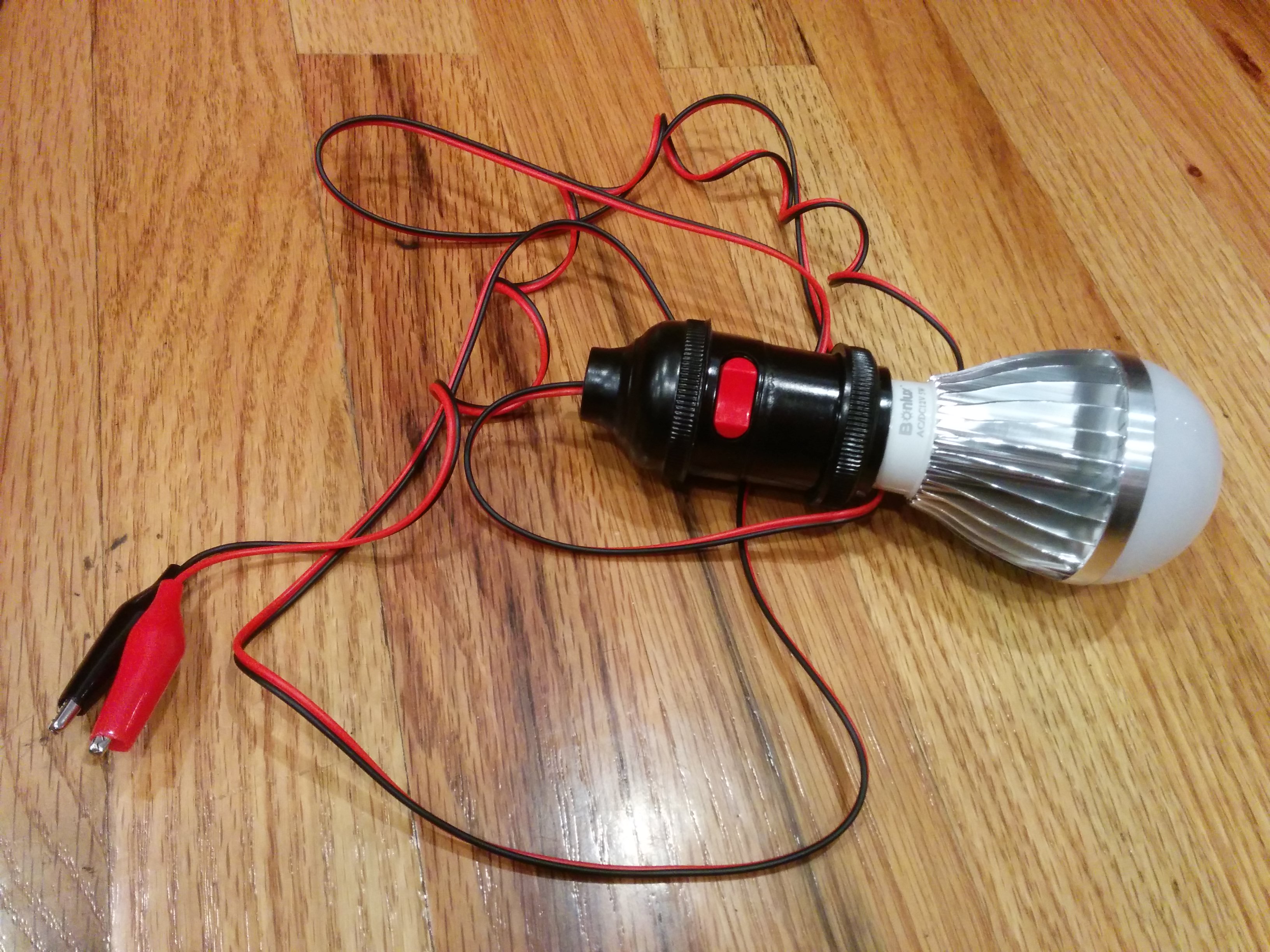
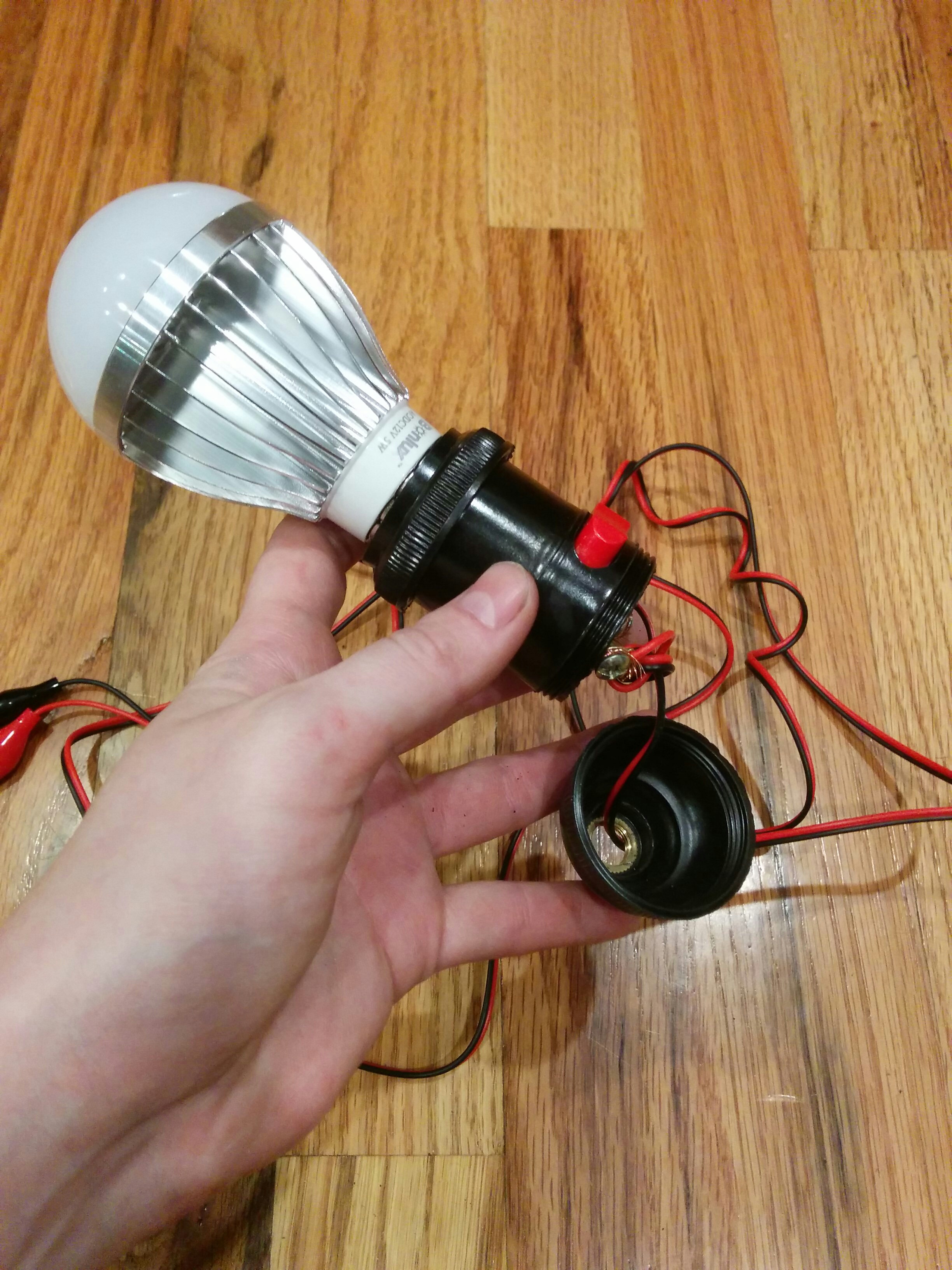
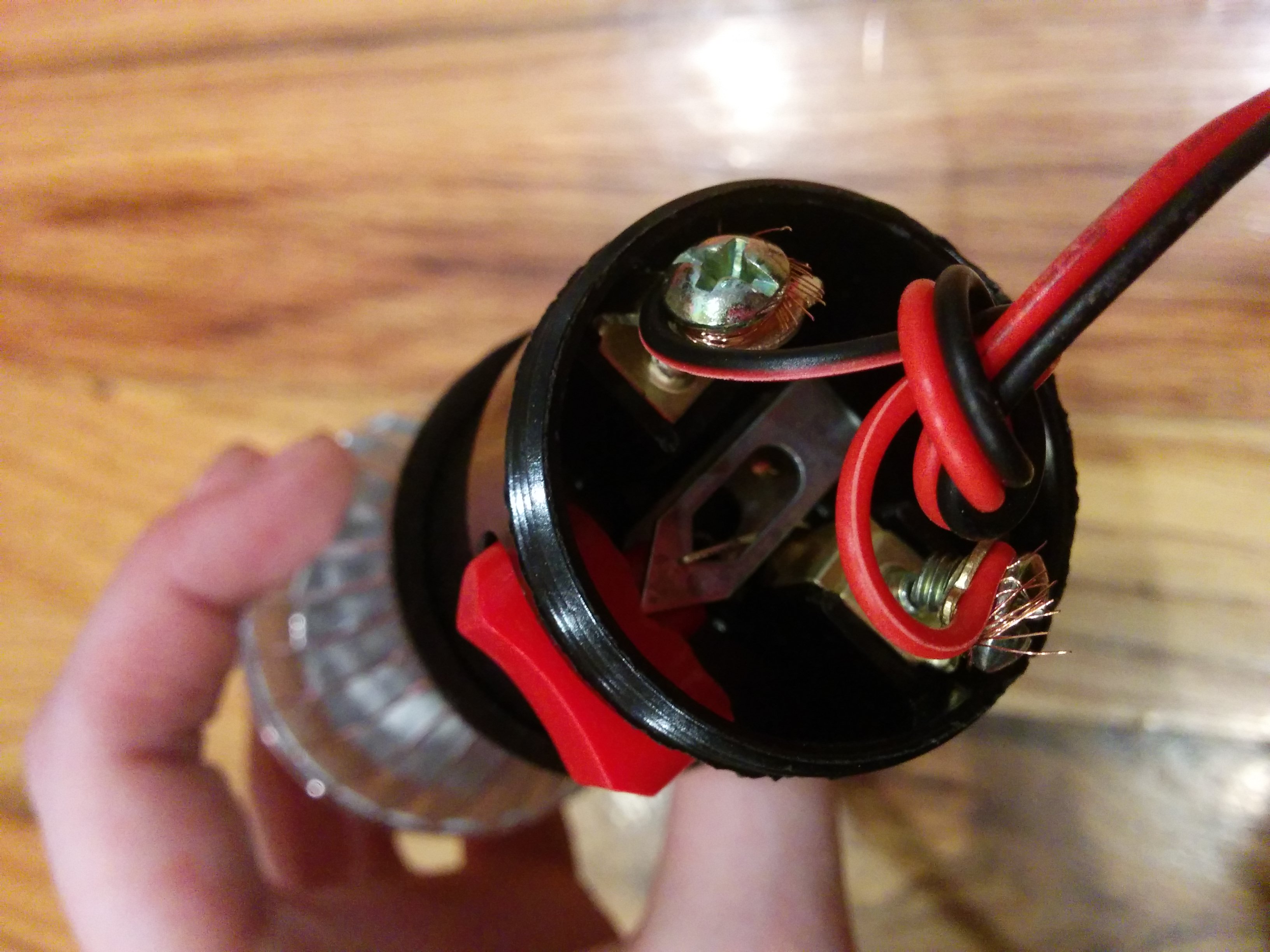
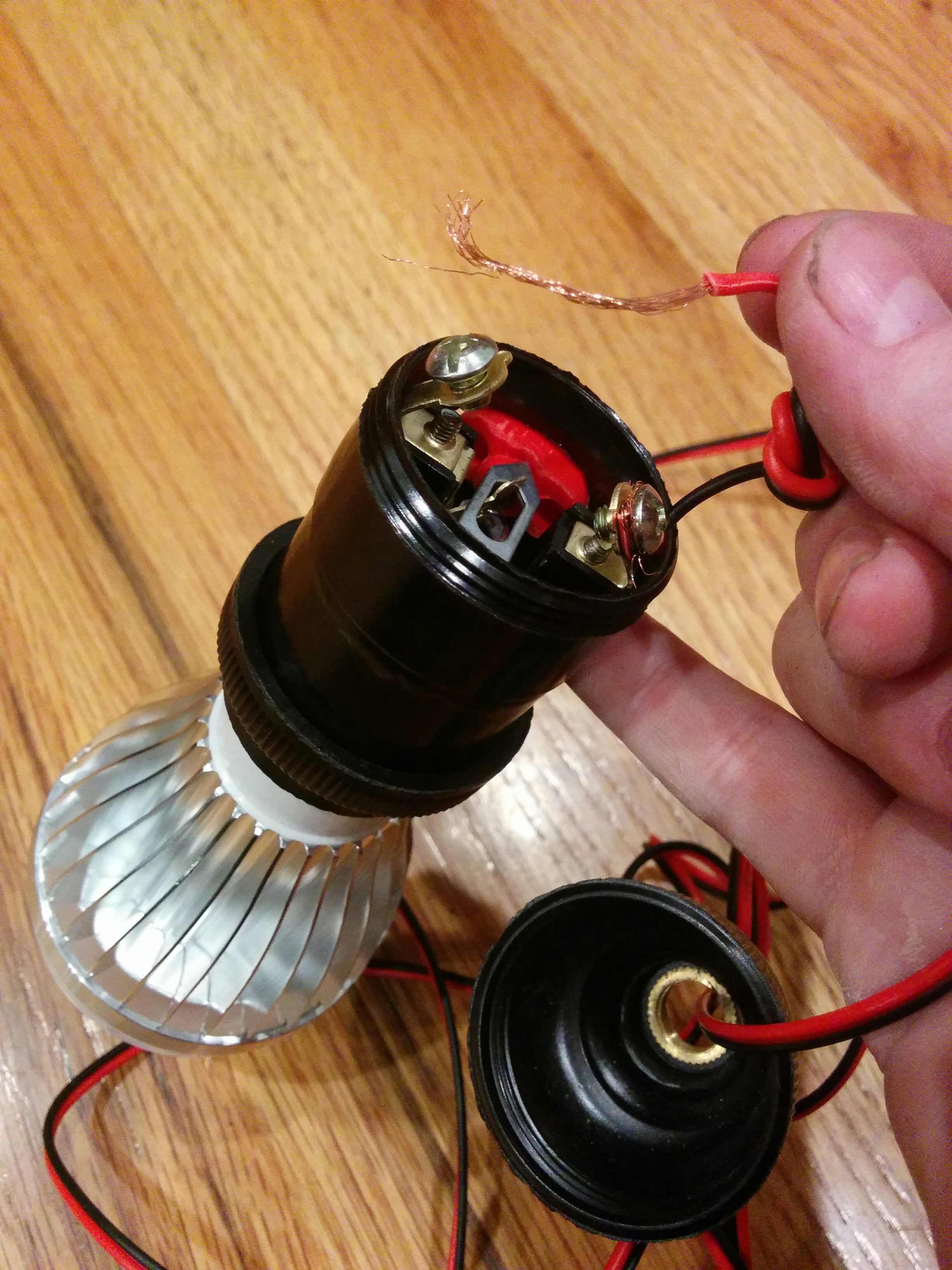
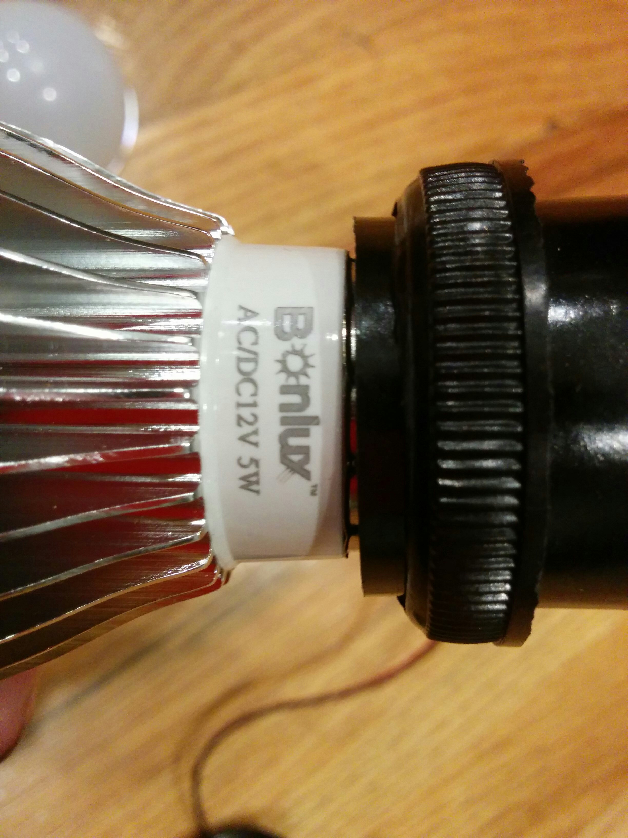
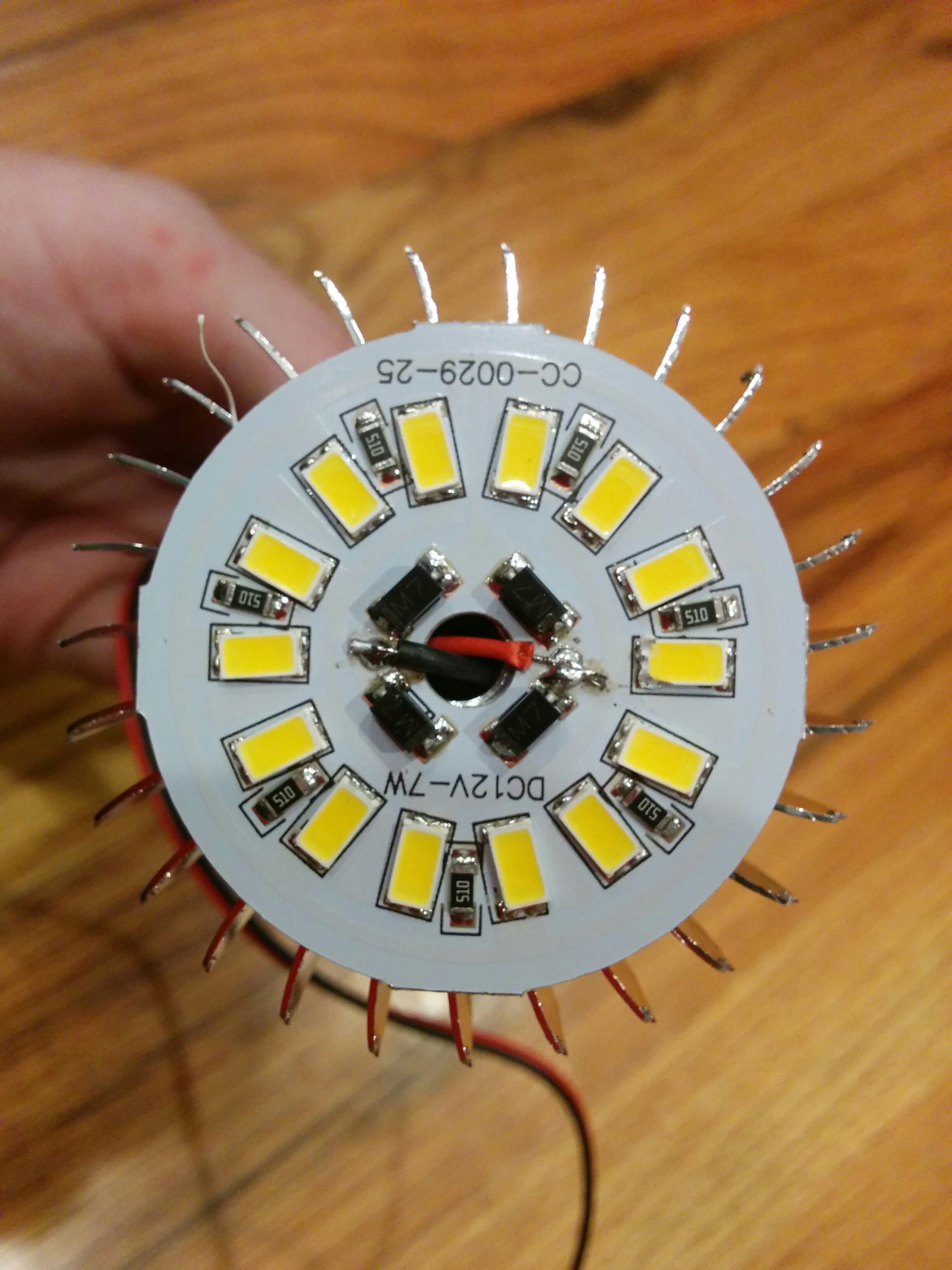
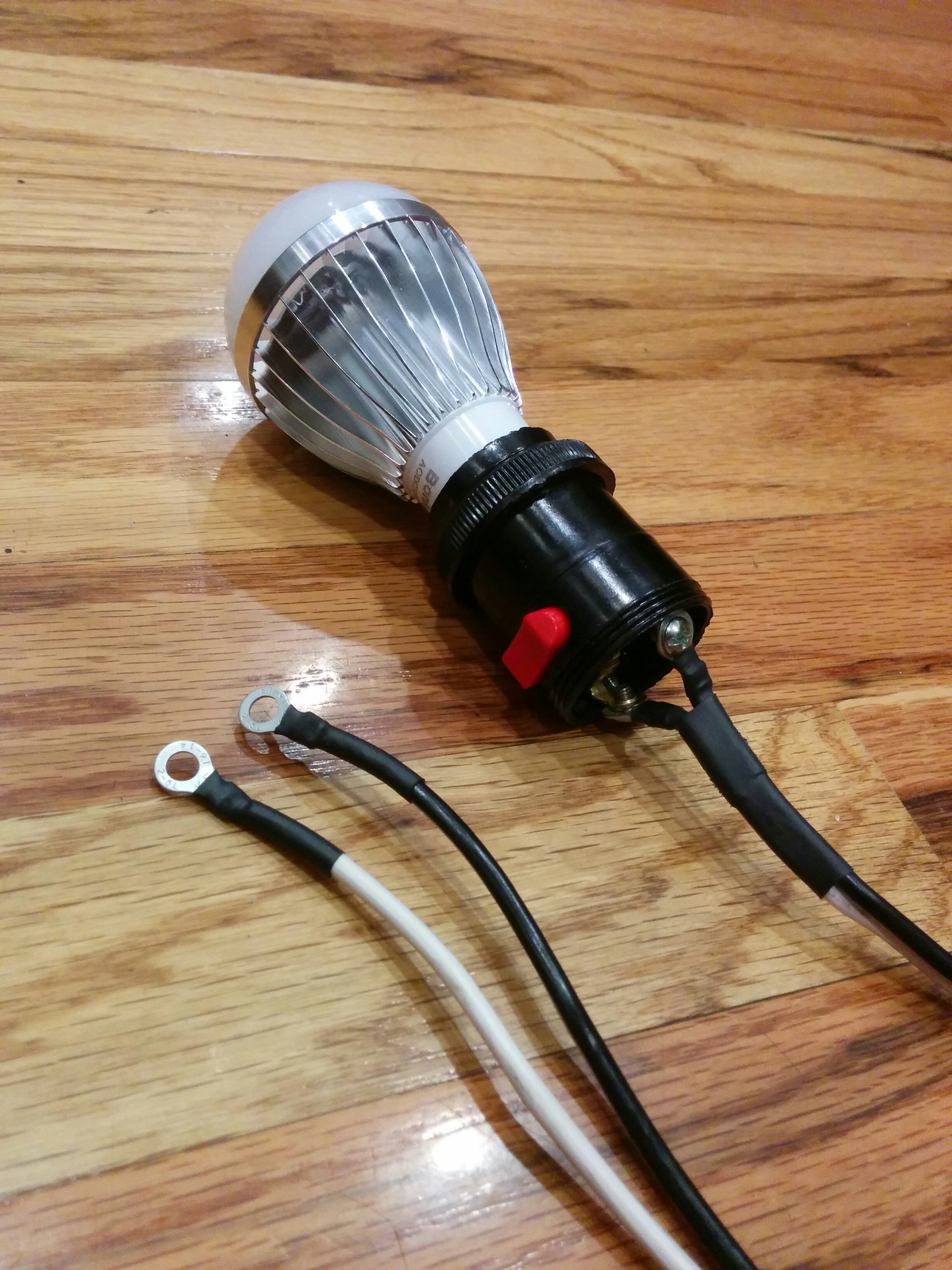
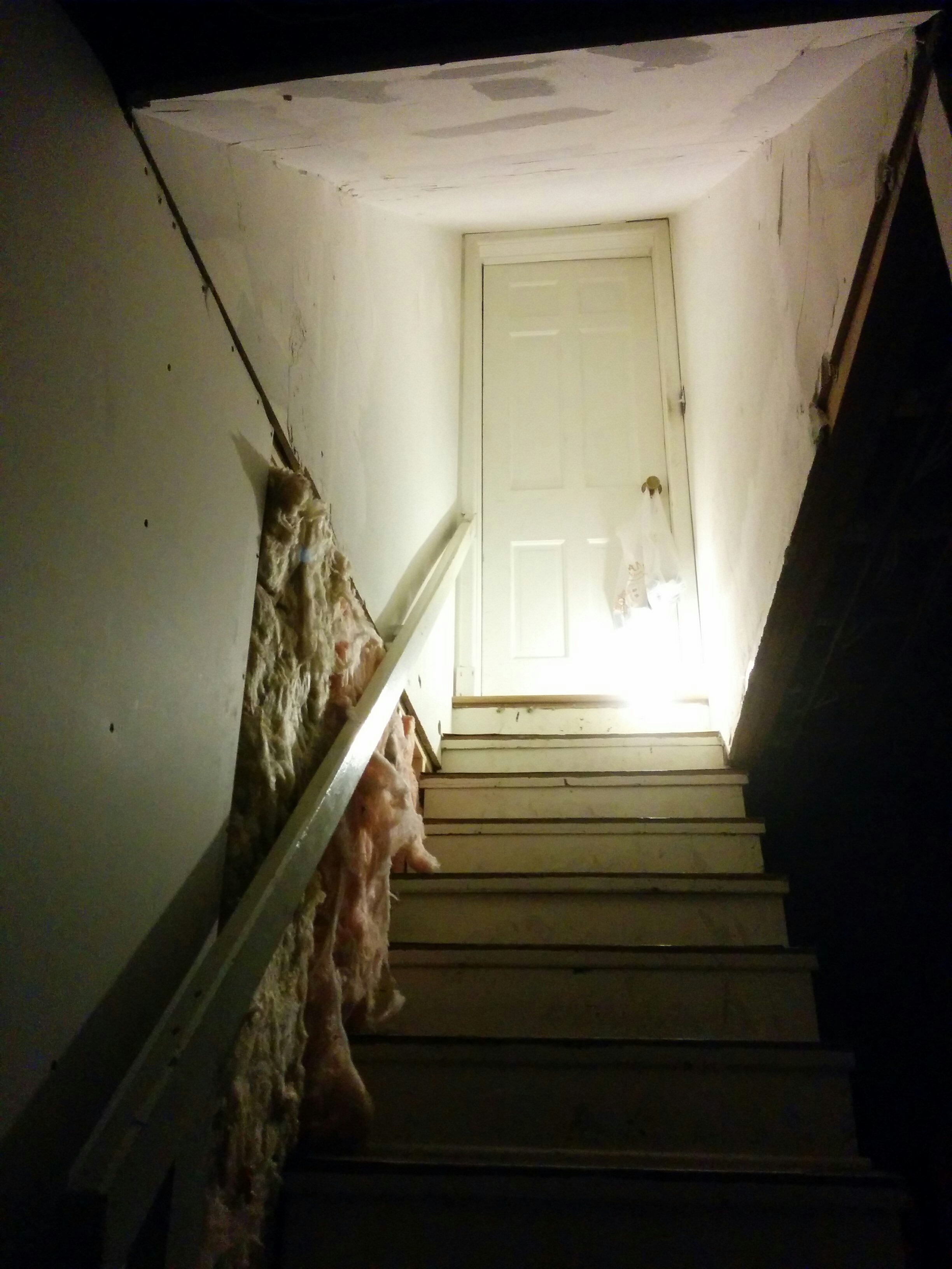
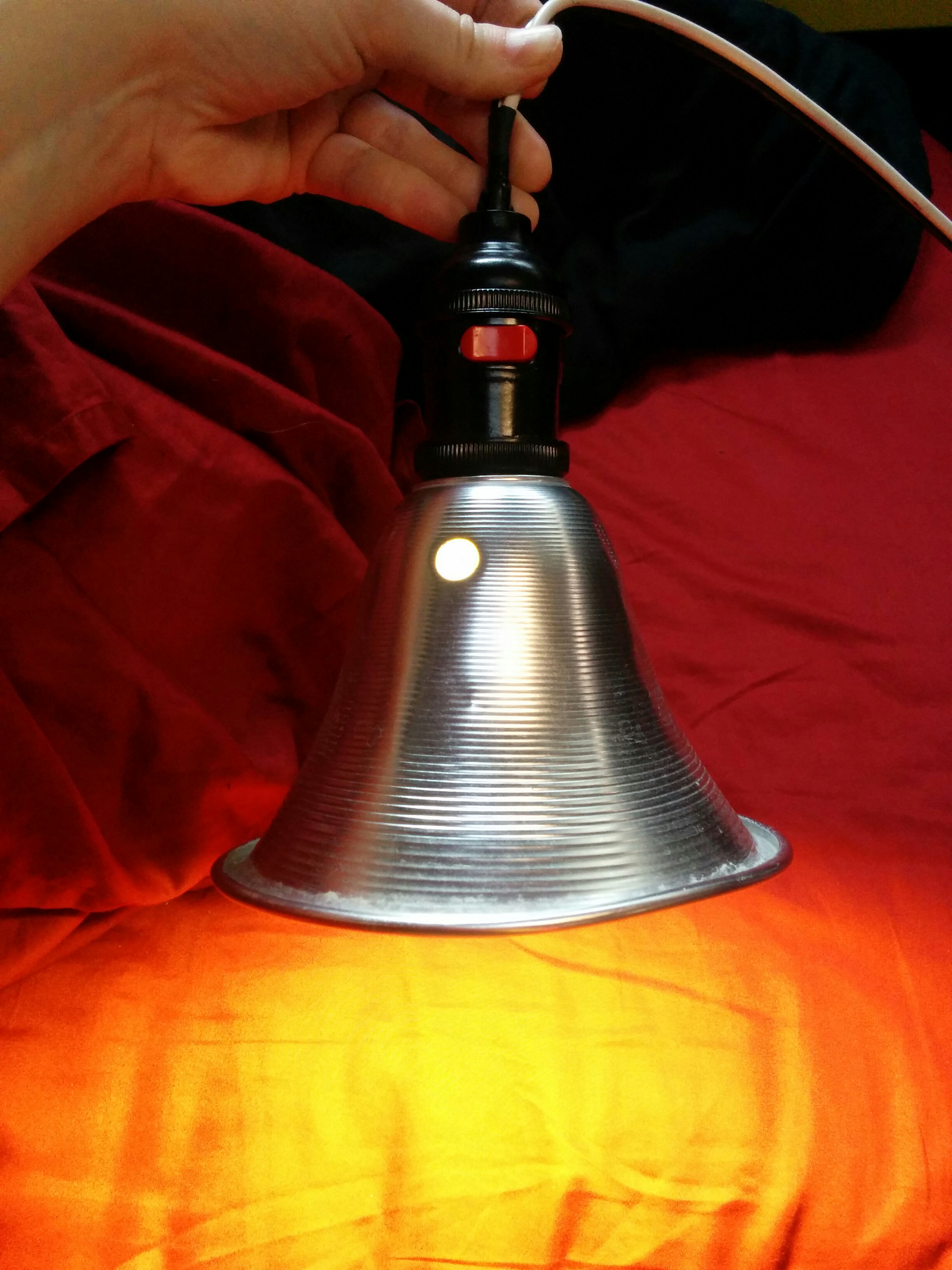
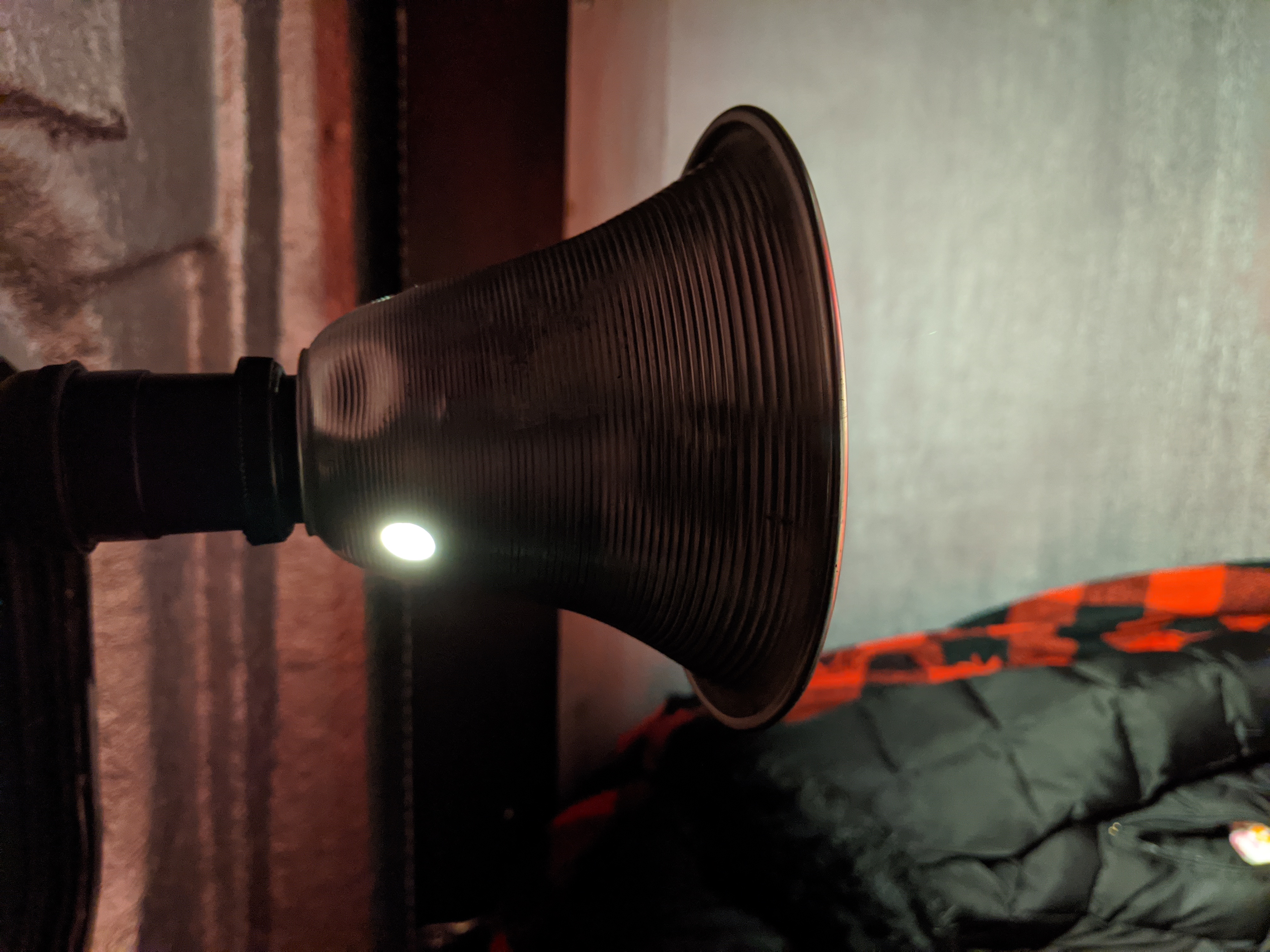
I tested the light brightness in the basement and it seemed about what I wanted. This would become my “comfy bedtime browsing” lamp that I would hang off the sunroof handle. I wouldn’t have to even get out of bed to turn it on, but I could also turn it on easily upon entering the van.
I also wanted a brighter and more comprehensive light for when I really needed to light the place up for a full scale rummaging.
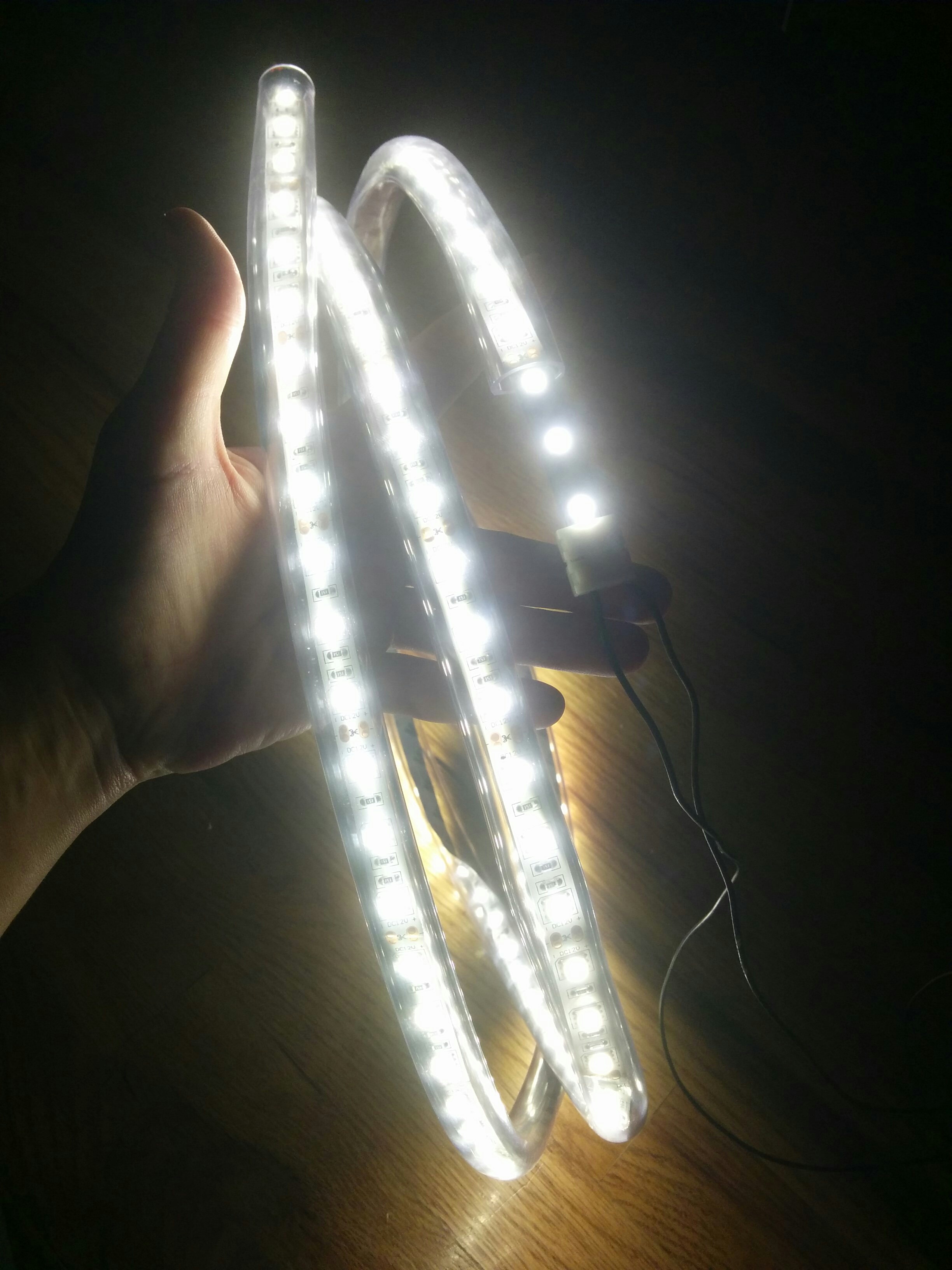
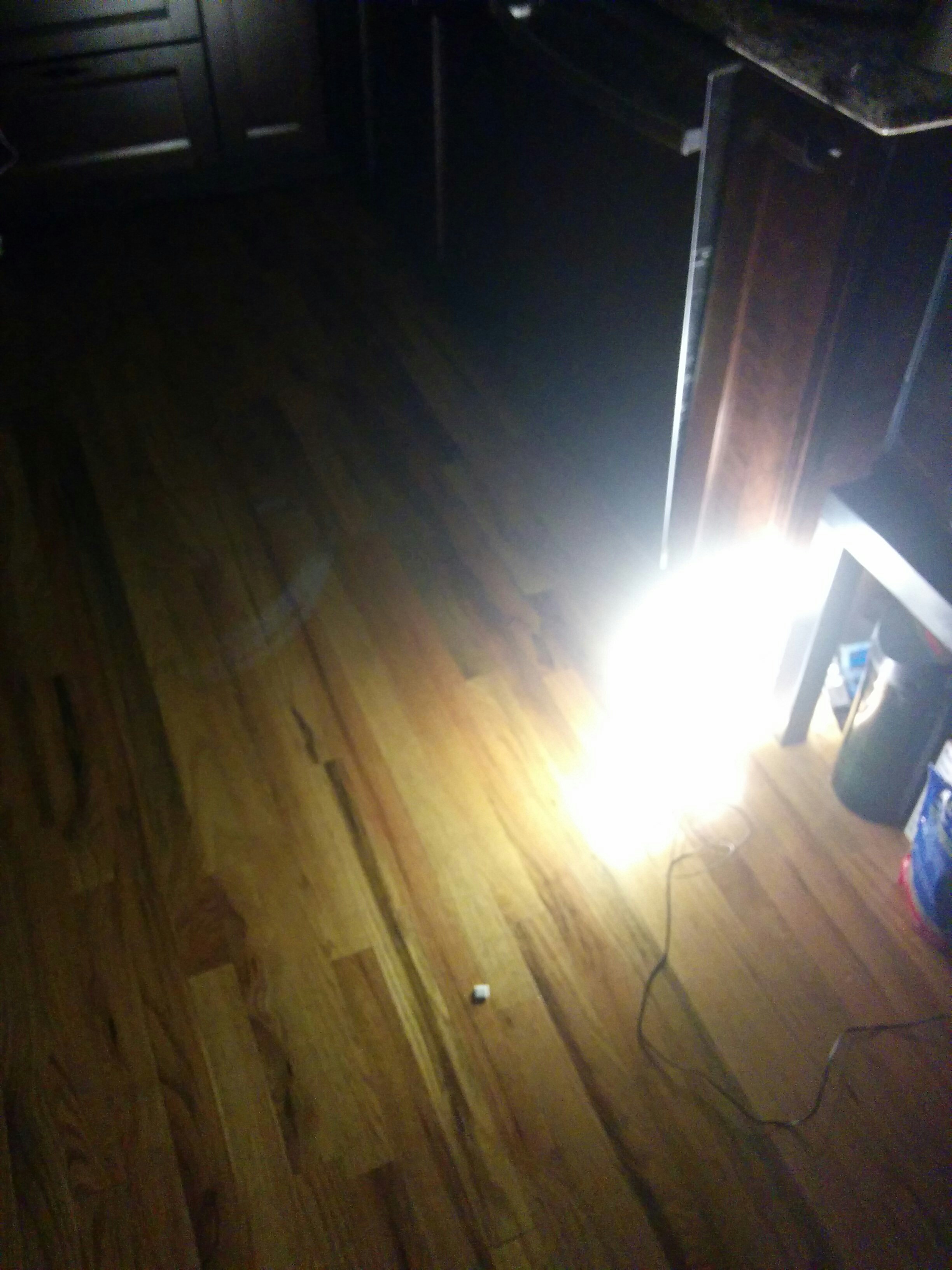
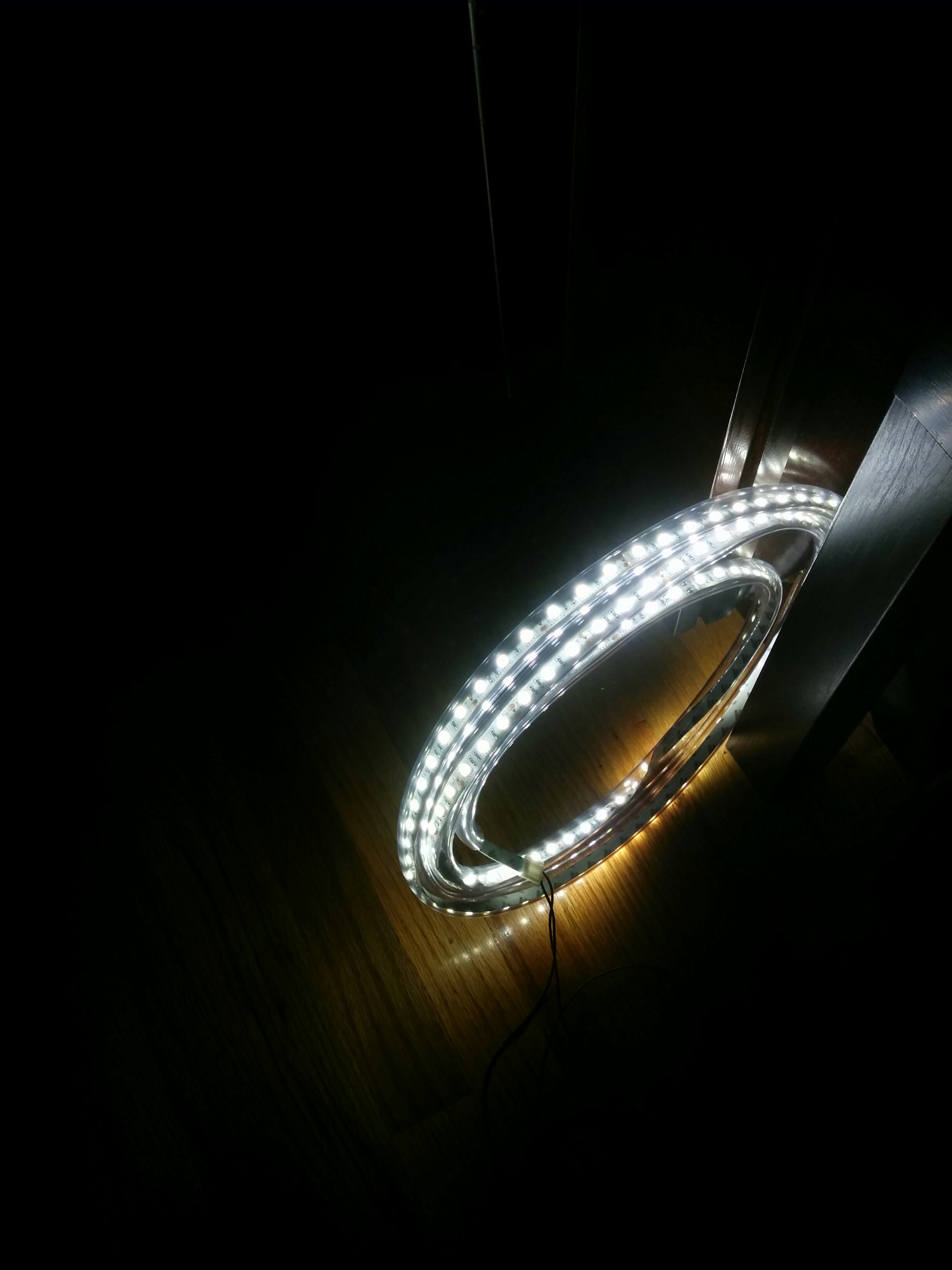
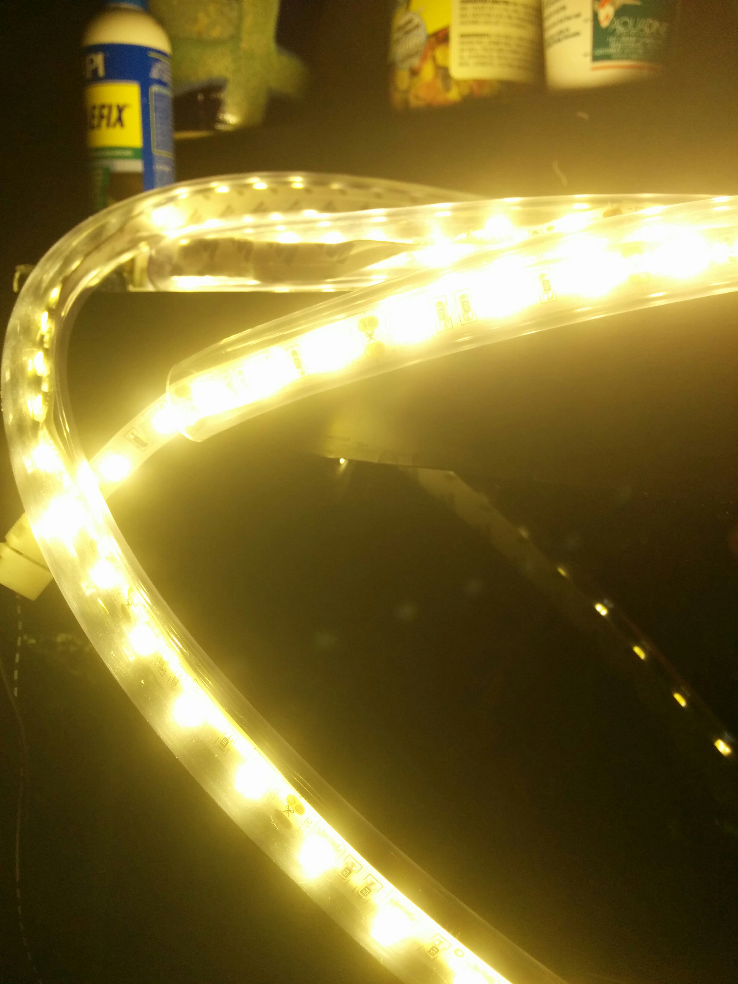
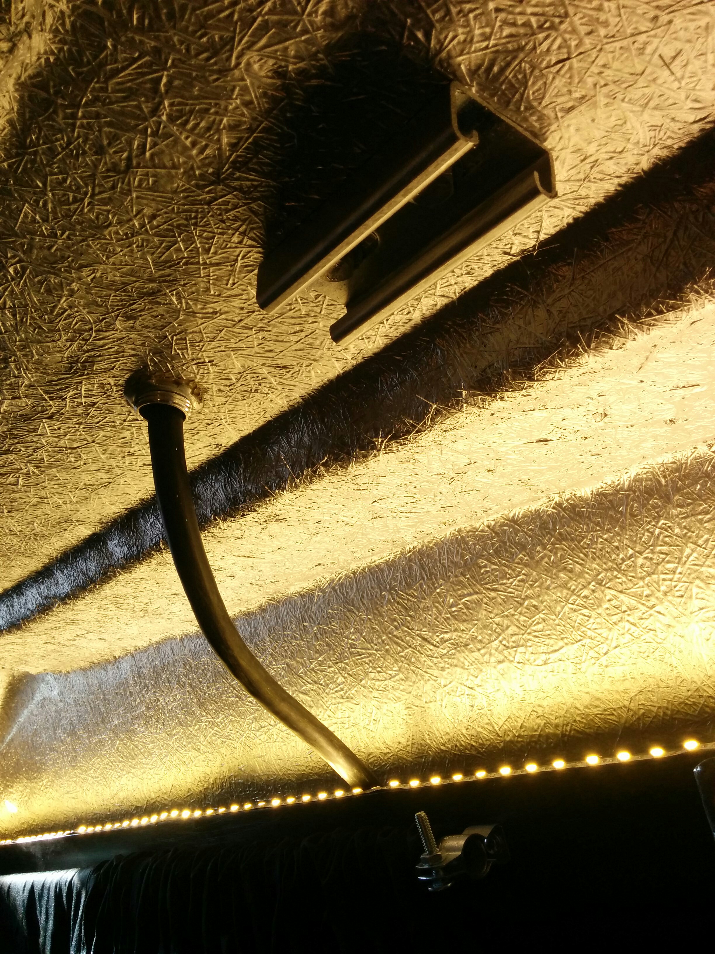
For this I got a cheapo 12V led light strip. Then I got a second one in “warm white” because the first was a bit too retina-searing. Here it is in some tubing (because I thought I would chuck it in the “gutter” behind the runner boards) but since it was adhesive backed I wound up just sticking it directly right on top. It was a bit brighter with all the leds facing upwards.
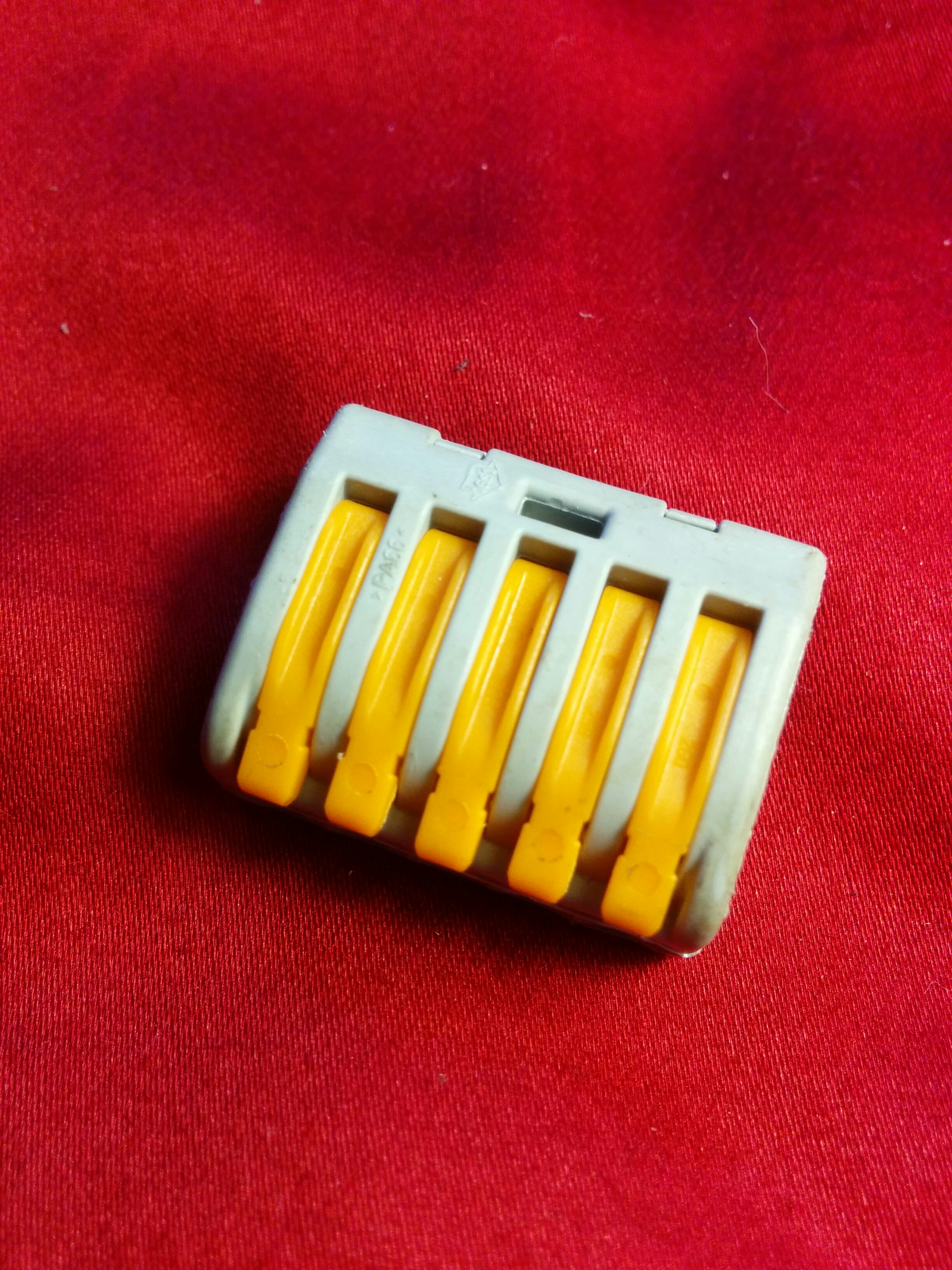
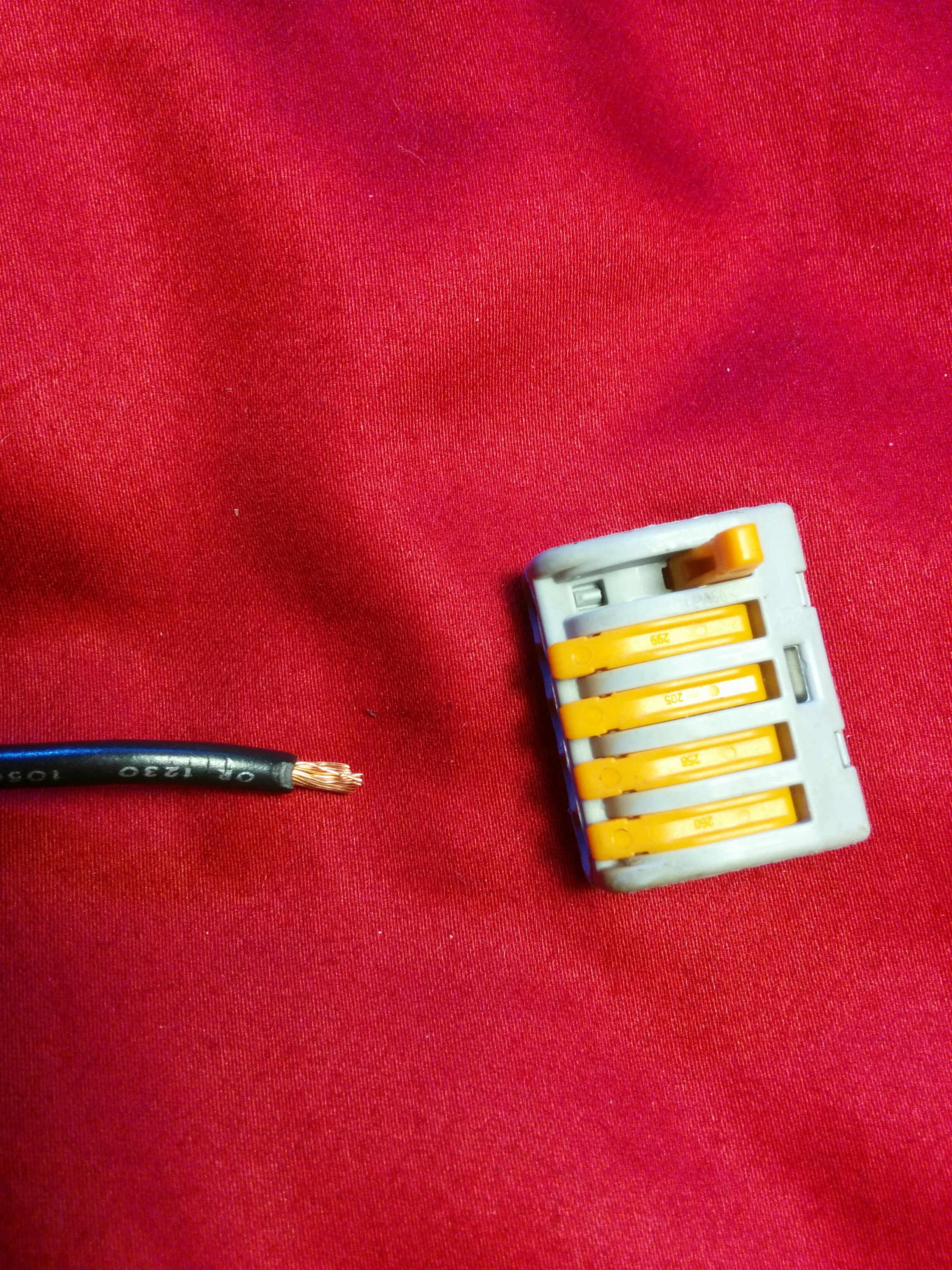
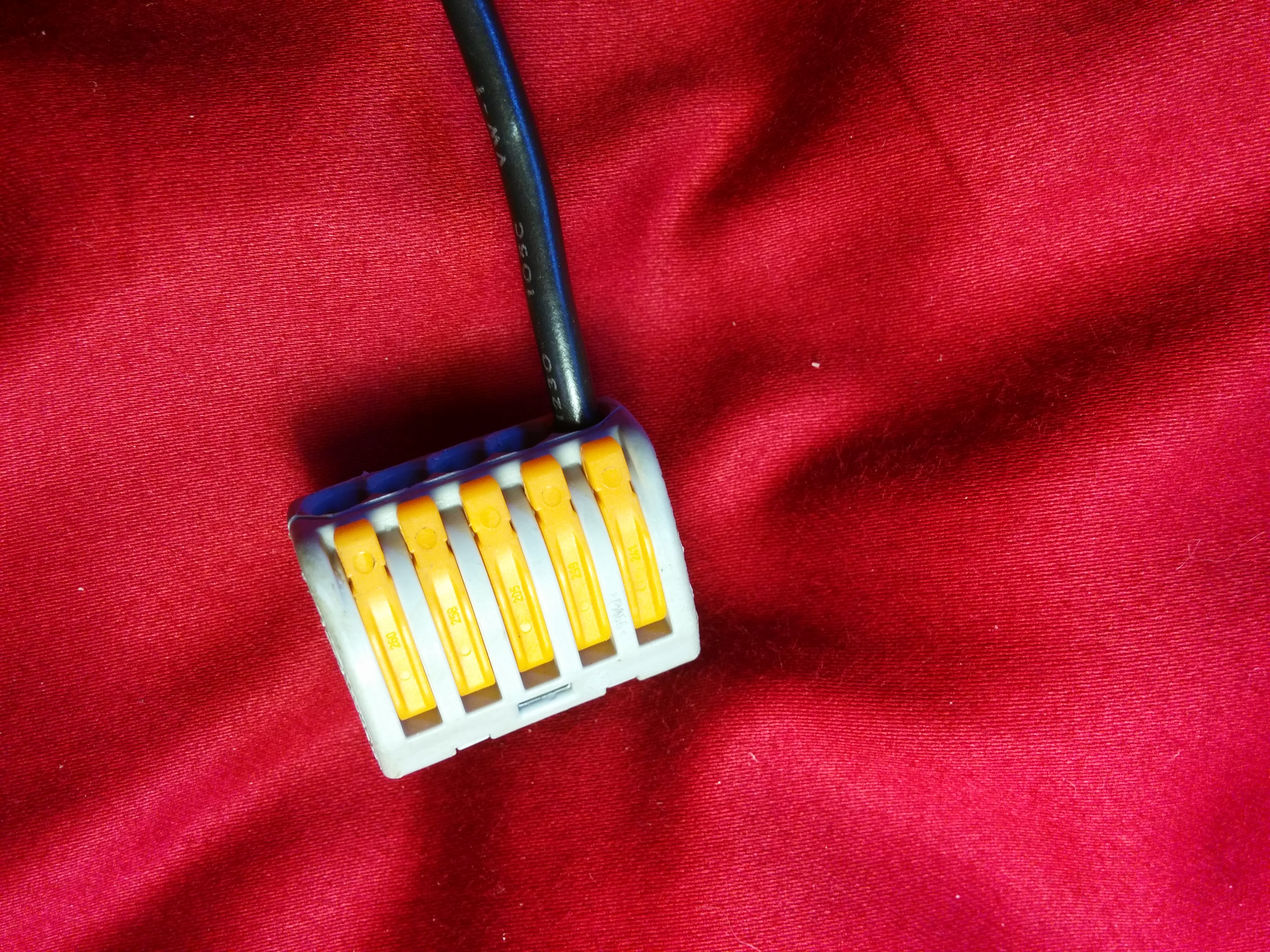
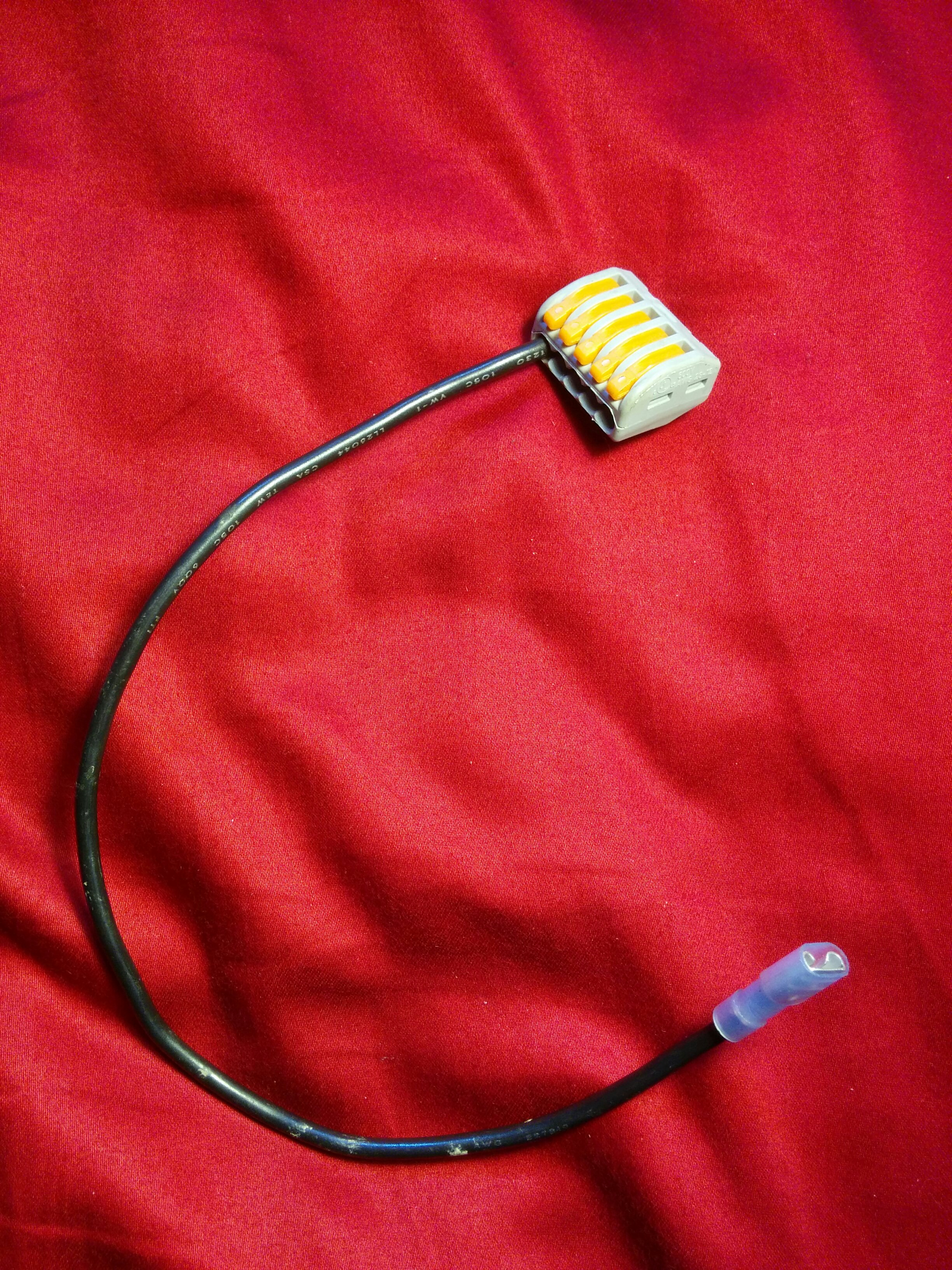
When it came time to install it in the van, I attached disconnects to the end of the led wires and then used these grey quick connect thingies I’d found at Menard’s to attach it to the 12V fuse block on the powershelf. These were basically common busbars for small wires in a more portable format and would let me extend my led wiring to both sides at a later point.
Power Control Box
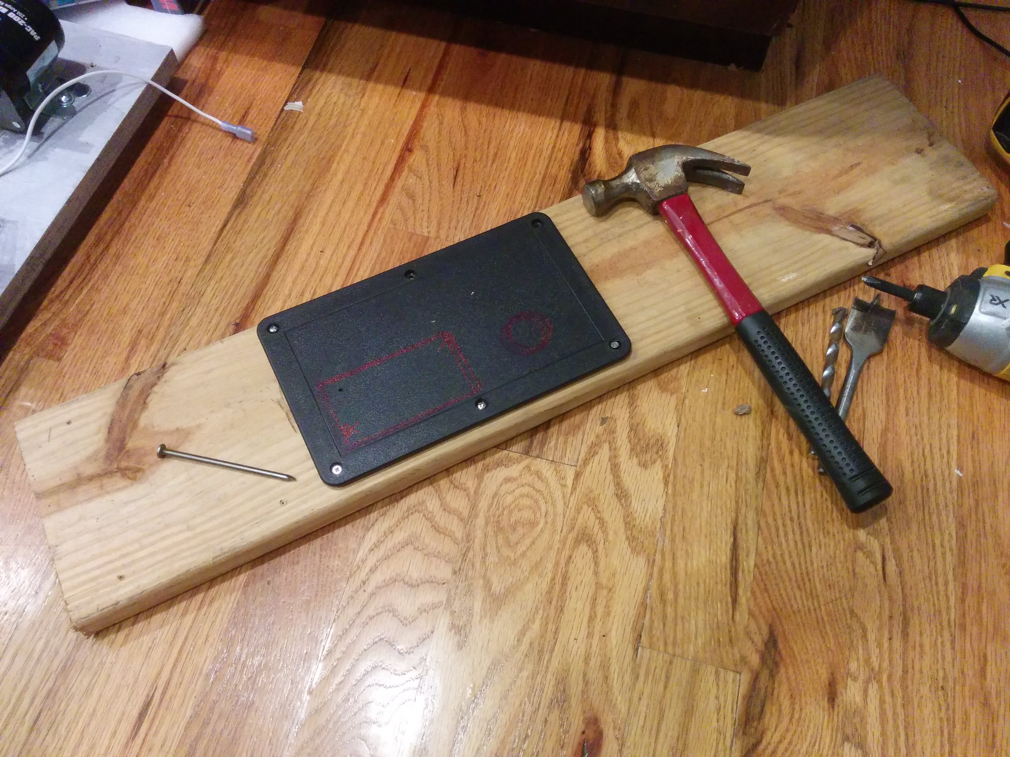
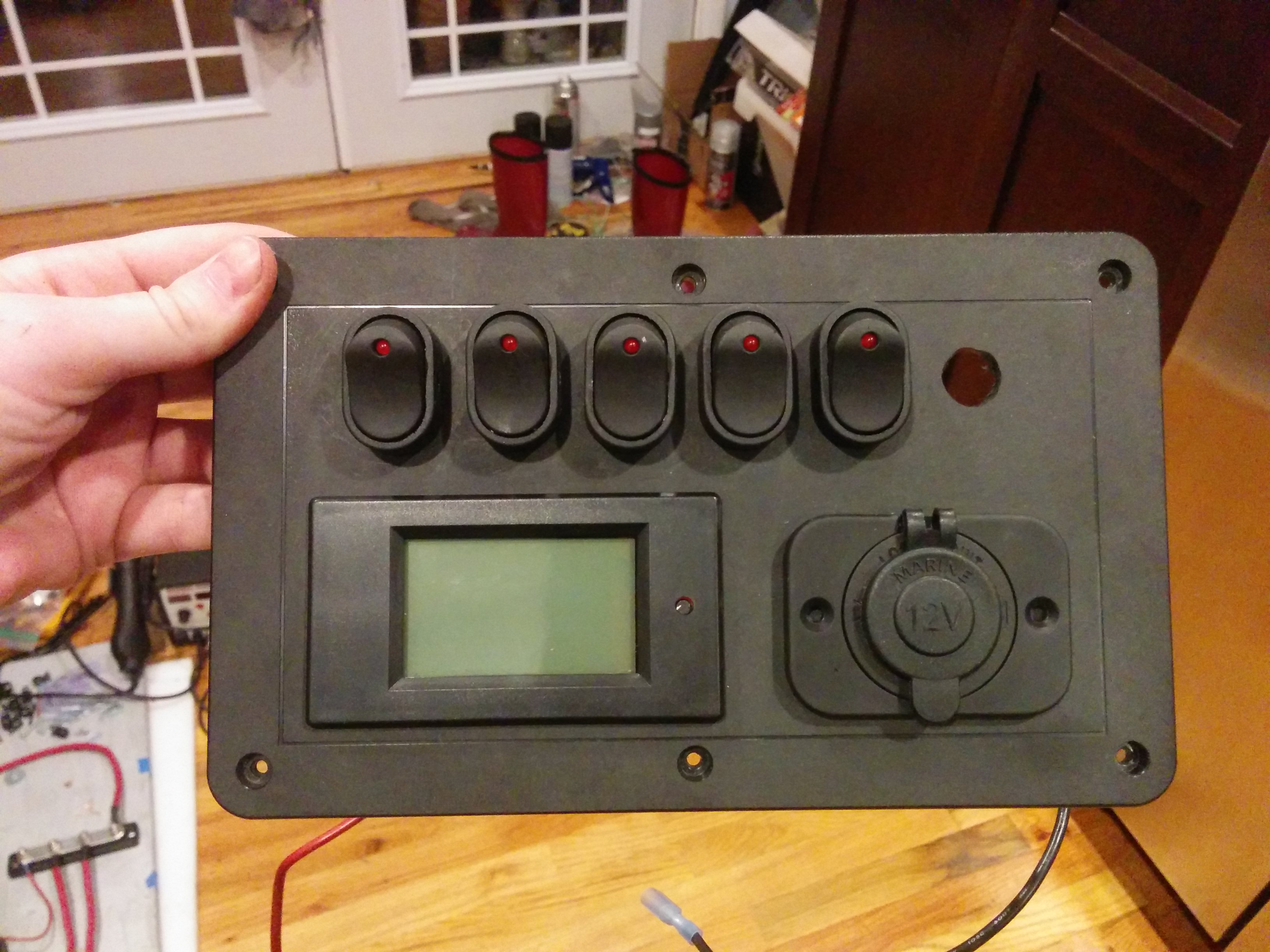
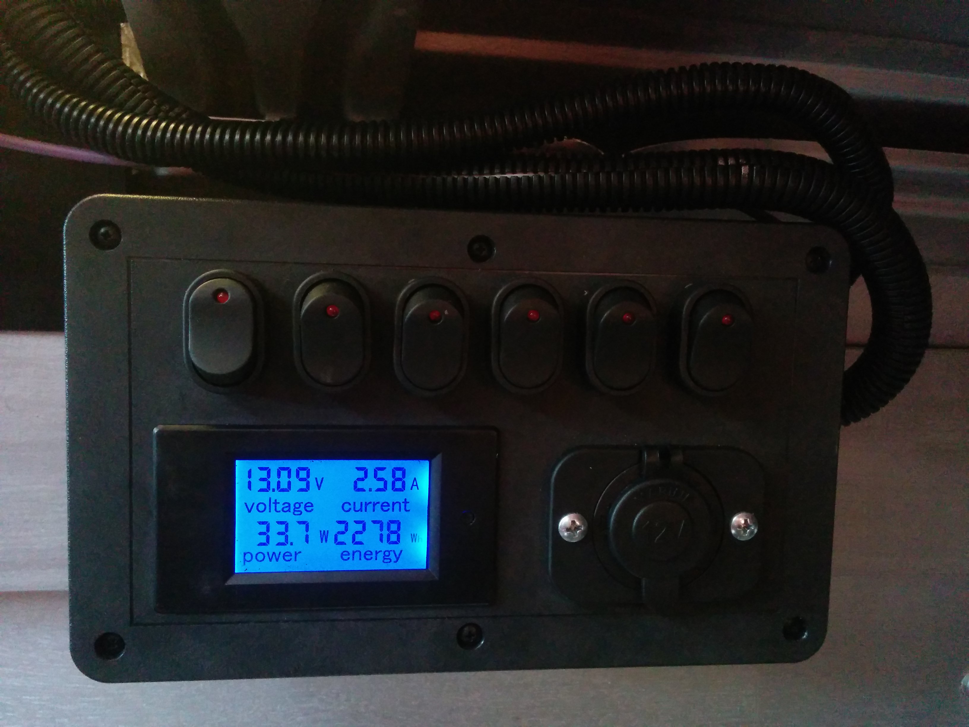
I wanted a way to control the lighting and have the power system data available at a glance. For this, I bought a plastic “utility box” on Amazon that seemed roughly the right size, the led display seen above, and some rocker switches. I would need to drill out the holes in some way, but it was not immediately clear to me how to go about doing this in a controlled fashion.
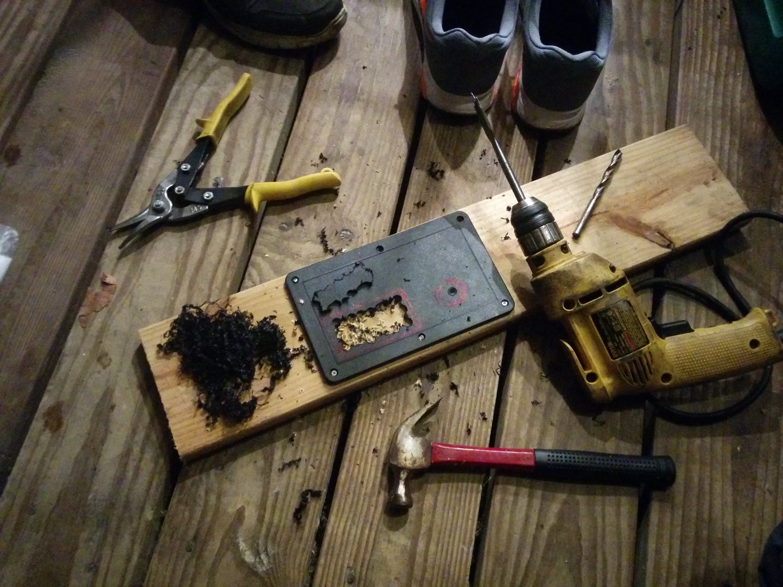
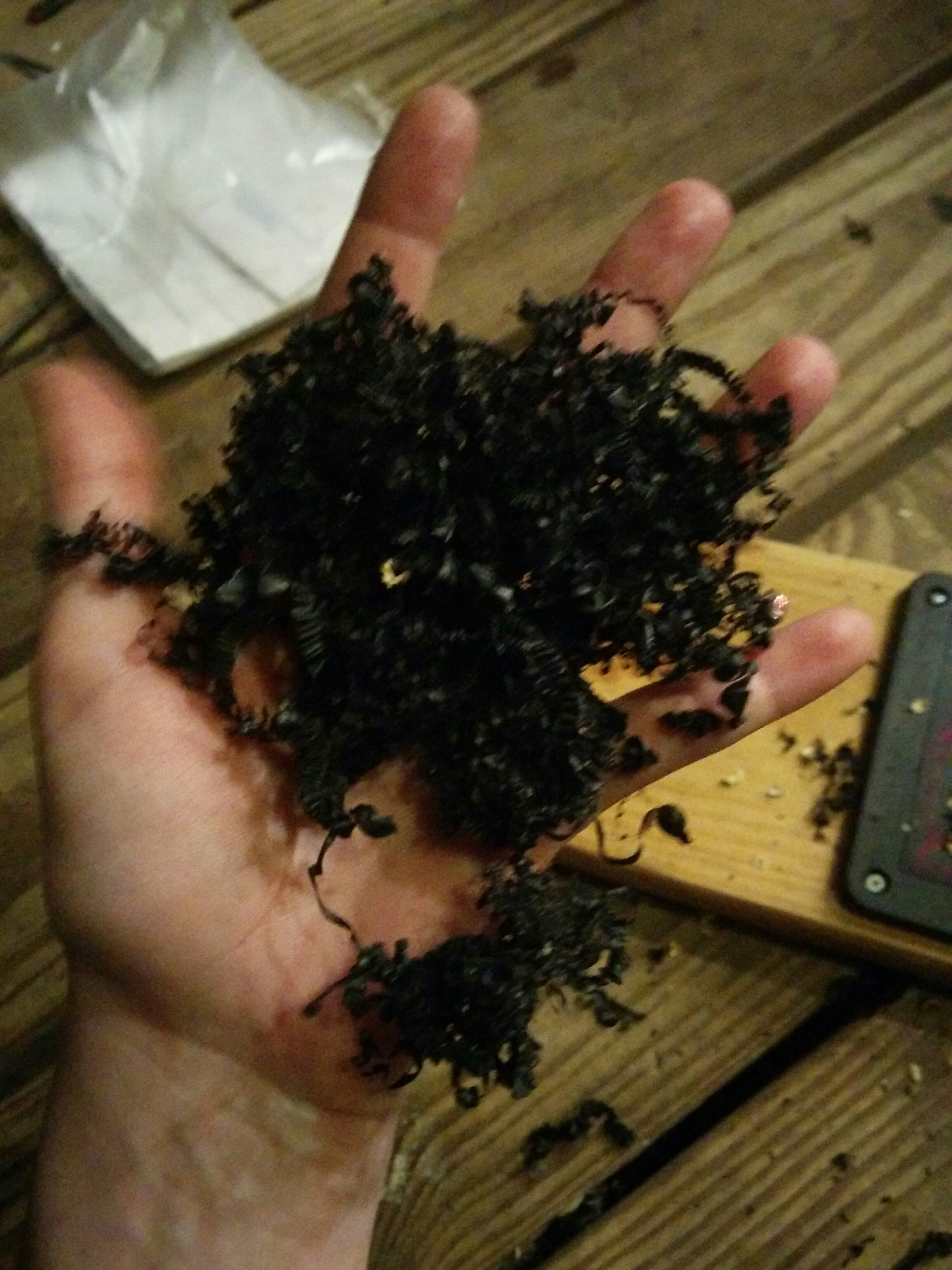
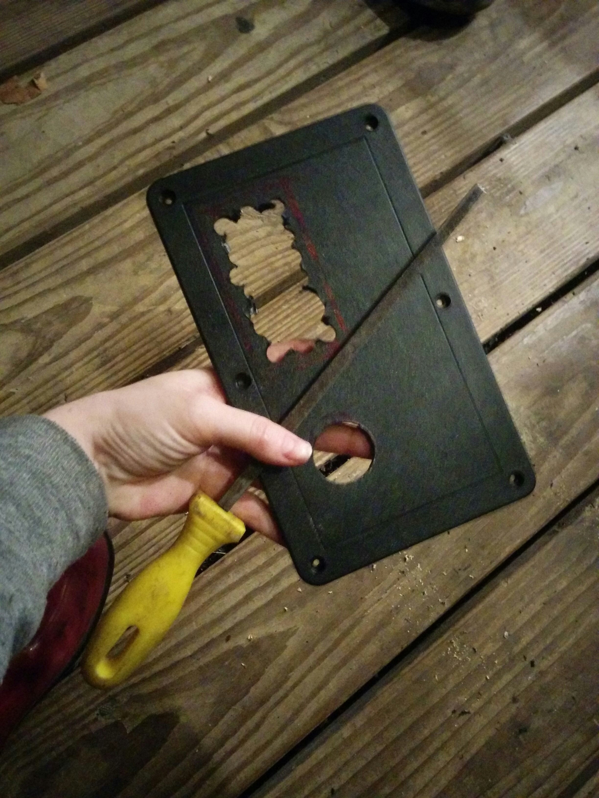
At first I tried to hold it myself and drill it but quickly realized this was not viable. I would need some way to secure it in place…the easiest way to do this with methods I had readily to hand was to screw it to a board. At the suggestion of a friend, I took a drill with a “spade bit” and removed the bulk of the inside of the square and drilled a pilot hole where the 12V cigarette lighter would go to help center the full size spade bit point. (TIL: “spade bits.”)
After the bulk was removed, I slowly and tediously used a file to trim it down to size. I later drilled several more holes along the top with a similar strategy (small pilot hole, followed by full size spade bit) so I could install rocker switches to control my led lights.
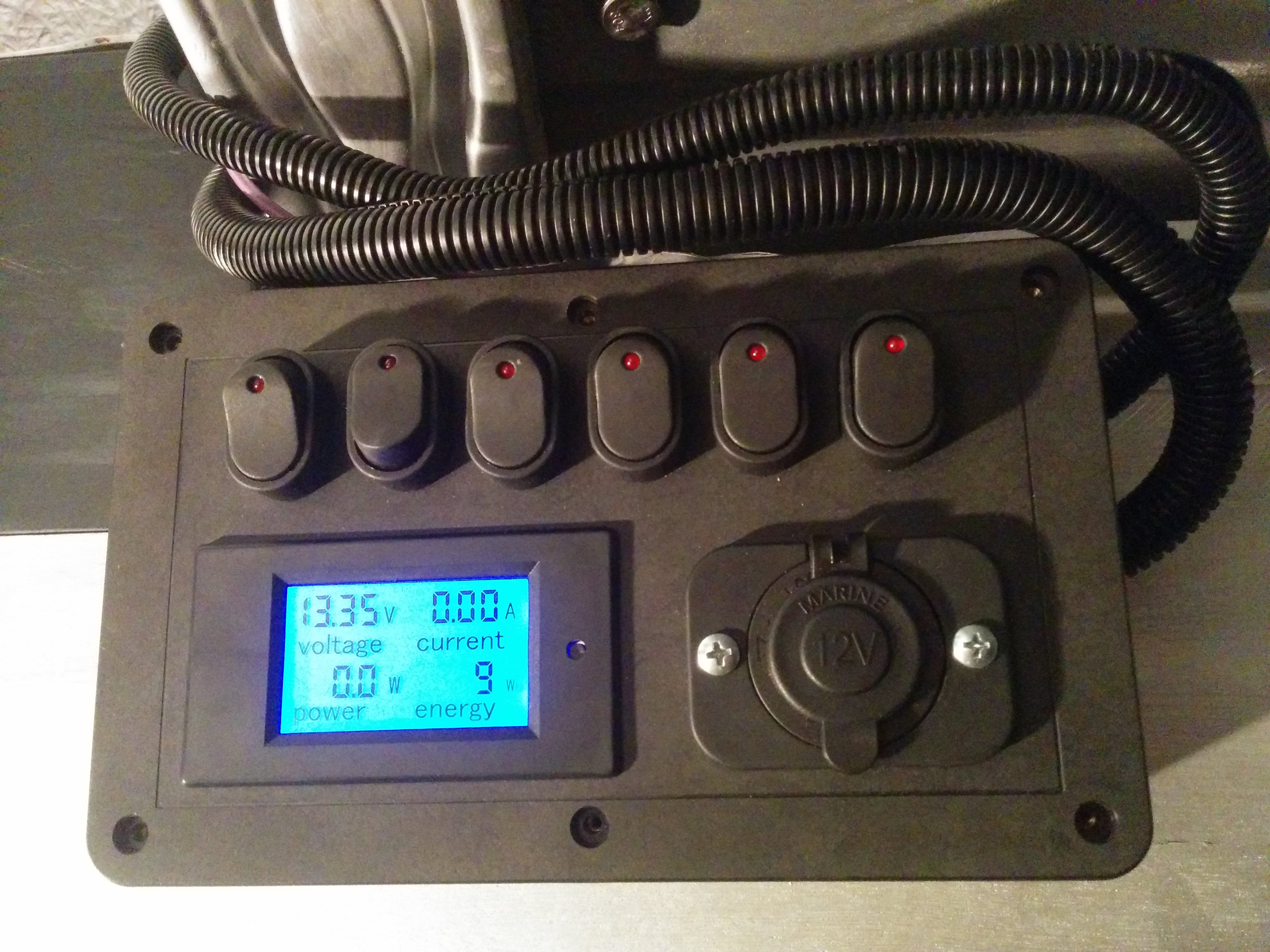
Just about ready to be mounted to the runner boards in the van.
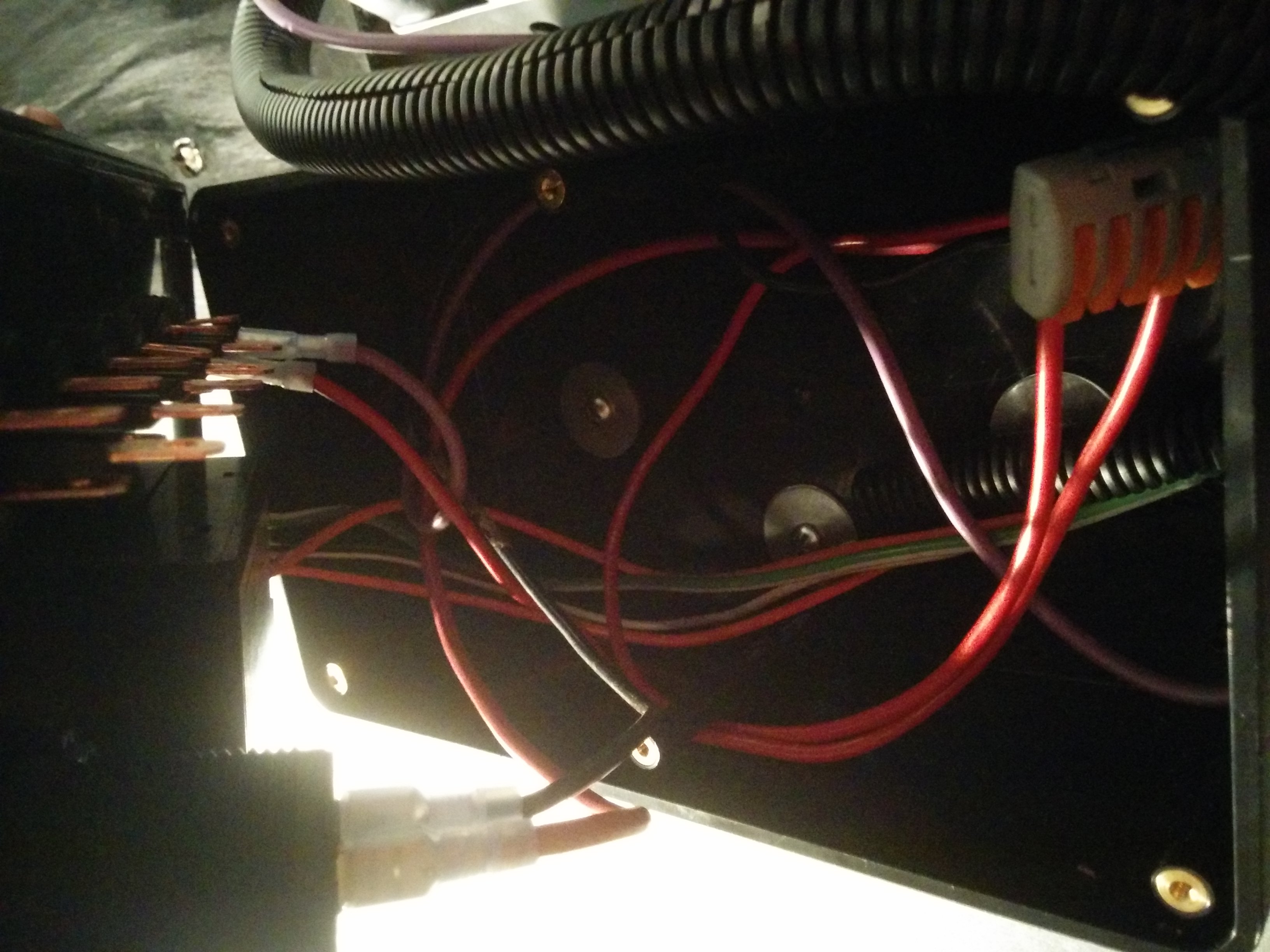
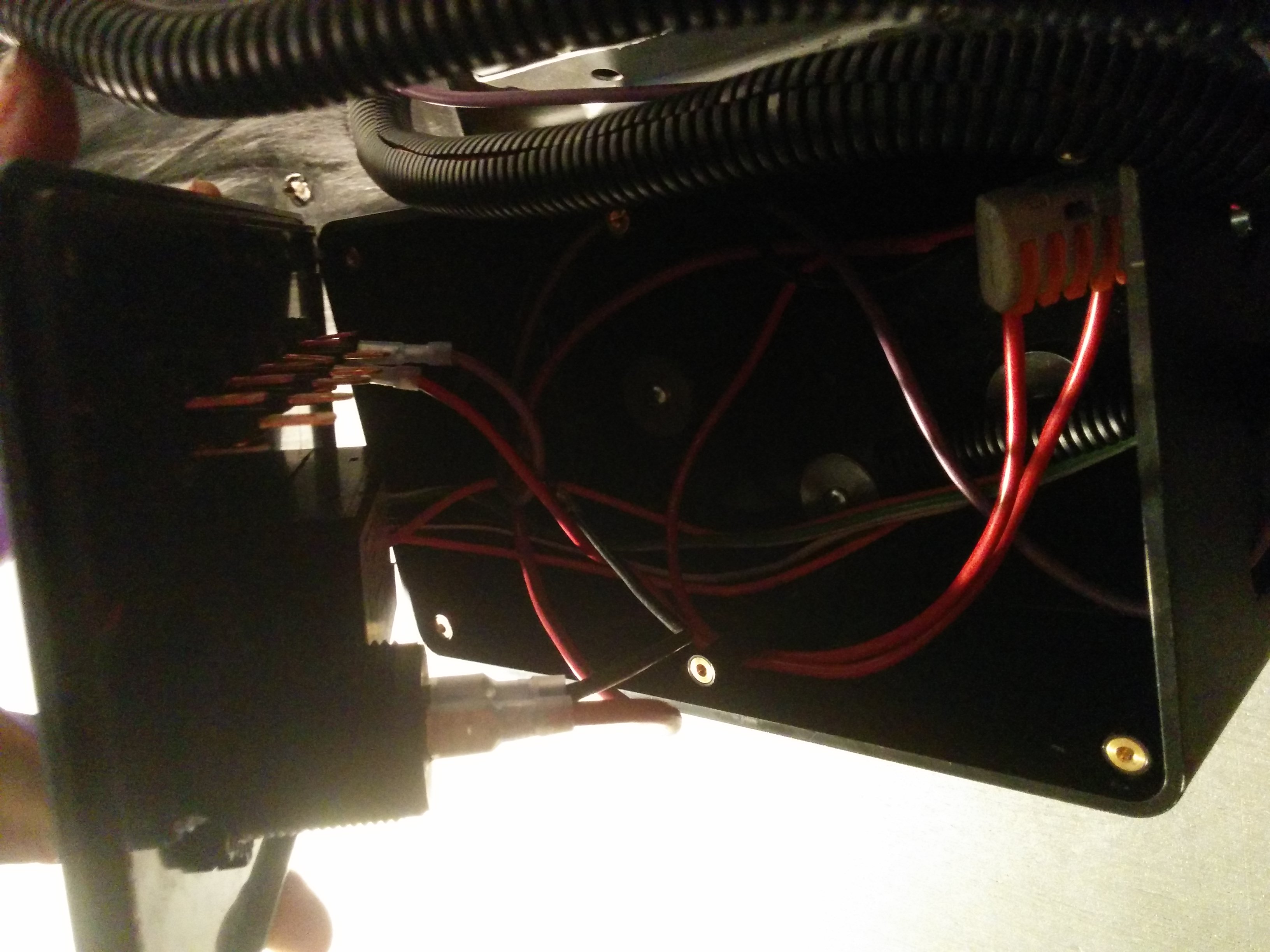
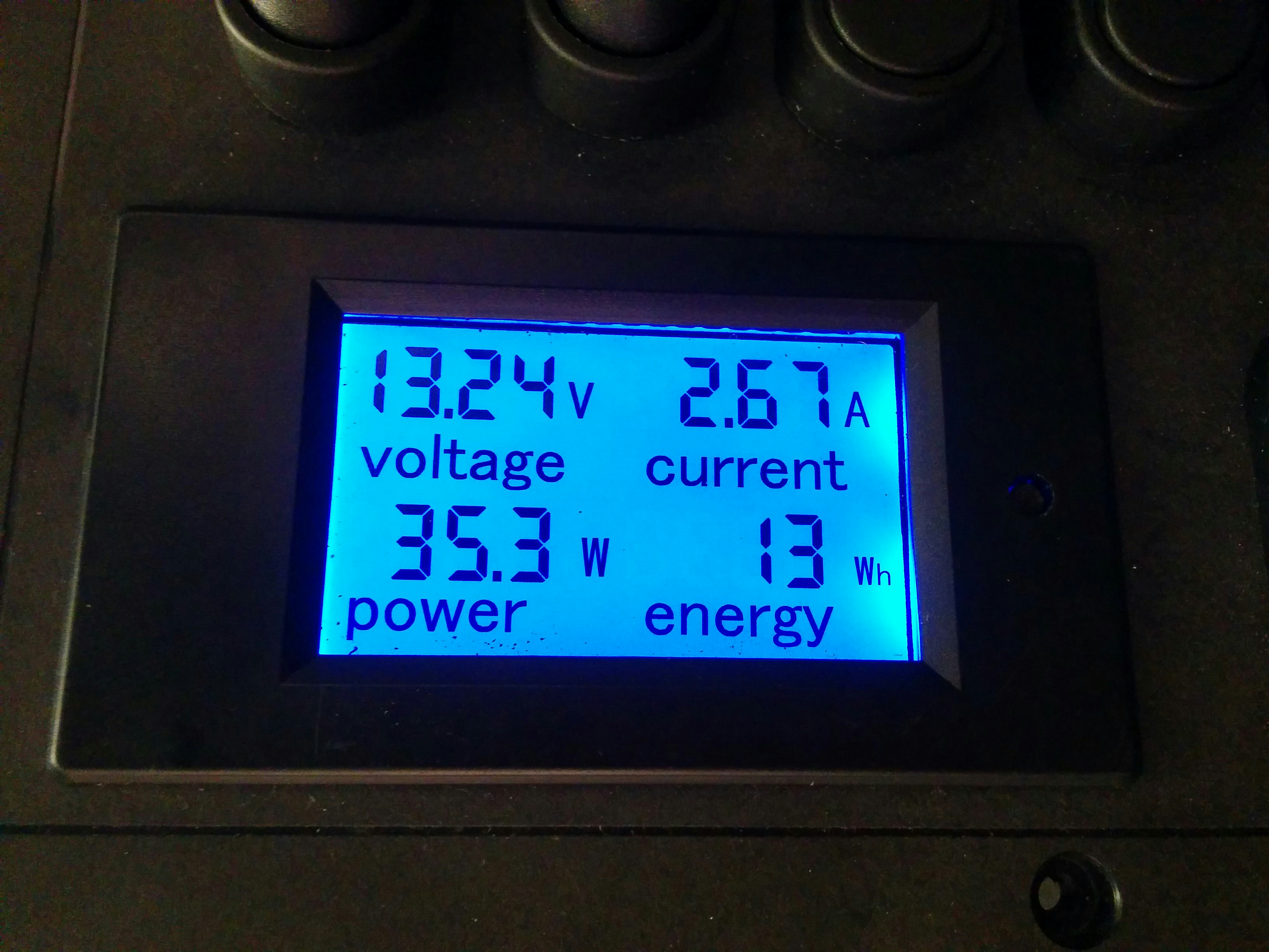
The leftmost switch controls the led tape lights. (The bulb has its own switch.) It looked like a total trainwreck with the wires everywhere so I got some black “cable loom” to help contain things. All the telemetry cables and the led striplight cables had to come into the box to either get switched or connect to the display.
When I got to the point that I could work on the van using the light from the LiFePO pack I was very extremely excited.
